


Tikzには、基本的なものから複雑なものまで、便利なデジタル回路部品がたくさんあります。ここでは、いくつかの私自身の、必ずしも便利なものばかりではありません。しかし、かなり便利な例を 1 つ挙げてみましょう。マグニチュード コンパレータです。
これが欲しいマグニチュードコンパレータタスクのコンポーネントで、信号ポートがanchorsとして定義されています。ポートにラベルを付けて名前を付けたボックスを作成できますが、足りない!
内部に何があるのかも示す必要があります。詳細はゲートを超えてはなりません。トランジスタは周囲に置きたくないのですが、ゲートは必要です。
今のところ私が持っているもののほとんどは、この(有名な?)データフリップフロップの例:
\makeatletter

% Magnitude Comparator (magn comparator) shape
\pgfdeclareshape{magn comparator}
{
    % The 'minimum width' and 'minimum height' keys, not the content, determine
    % the size
    \savedanchor\northeast
    {%
        \pgfmathsetlength\pgf@x{\pgfshapeminwidth}%
        \pgfmathsetlength\pgf@y{\pgfshapeminheight}%
        \pgf@x=0.5\pgf@x
        \pgf@y=0.5\pgf@y
    }
    % This is redundant, but makes some things easier:
    \savedanchor\southwest
    {%
        \pgfmathsetlength\pgf@x{\pgfshapeminwidth}%
        \pgfmathsetlength\pgf@y{\pgfshapeminheight}%
        \pgf@x=-0.5\pgf@x
        \pgf@y=-0.5\pgf@y
    }
    % Inherit from rectangle
    \inheritanchorborder[from=rectangle]

    % Define same anchor a normal rectangle has
    \anchor{center}{\pgfpointorigin}
    \anchor{north}{\northeast \pgf@x=0pt}
    \anchor{east}{\northeast \pgf@y=0pt}
    \anchor{south}{\southwest \pgf@x=0pt}
    \anchor{west}{\southwest \pgf@y=0pt}
    \anchor{north east}{\northeast}
    \anchor{north west}{\northeast \pgf@x=-\pgf@x}
    \anchor{south west}{\southwest}
    \anchor{south east}{\southwest \pgf@x=-\pgf@x}
    \anchor{text}
    {
        \pgfpointorigin
        \advance\pgf@x by -.5\wd\pgfnodeparttextbox%
        \advance\pgf@y by -.5\ht\pgfnodeparttextbox%
        \advance\pgf@y by +.5\dp\pgfnodeparttextbox%
    }

    % Define anchors for input signal ports
    \anchor{input gt}
    {
        \pgf@process{\southwest}%
        \pgf@y=-.5\pgf@y%
    }
    \anchor{input eq}
    {
        \pgf@process{\southwest}%
        \pgf@y=0pt%
    }
    \anchor{input lt}
    {
        \pgf@process{\southwest}%
        \pgf@y=.5\pgf@y%
    }
    \anchor{input a}
    {
        \pgf@process{\northeast}%
        \pgf@x=-.3\pgf@x%
    }
    \anchor{input b}
    {
        \pgf@process{\northeast}%
        \pgf@x=.3\pgf@x%
    }

    % Define anchors for output signal ports
    \anchor{output gt}
    {
        \pgf@process{\northeast}%
        \pgf@y=.5\pgf@y%
    }
    \anchor{output eq}
    {
        \pgf@process{\northeast}%
        \pgf@y=0pt%
    }
    \anchor{output lt}
    {
        \pgf@process{\northeast}%
        \pgf@y=-.5\pgf@y%
    }

    % Draw the rectangle box and the port labels
    \backgroundpath
    {
        % Rectangle box
        \pgfpathrectanglecorners{\southwest}{\northeast}
        % \node [and gate] (kek) at (0, 0) {};
    }
}

% Define default style for this node
\tikzset
{
    every magn comparator node/.style =
    {
        draw,
        minimum width = 2cm,
        minimum height = 2cm,
        thick,
        inner sep = 1mm,
        outer sep = 0pt,
        cap = round
    }
}

\makeatother
これは、メインの LaTeX ファイルのプリアンブルに含める別のファイルです。
ここにはゲートはなく、ボックスを描くだけです。私は、このものの外でいつものようにランダムな AND ゲートを配置しようとしましたが\pgfdeclareshape、もちろんうまくいきませんでした。その試みをコメント アウトしました。
既存の図形の上にさらに図形を定義する方法があるはずです。それは何ですか?
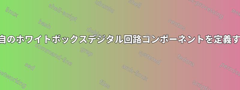
編集:私は、AND/OR/NOR/XOR/NAND ゲートと同様に、アンカーとして簡単にアクセスできるポートを配置できる次のようなものを手に入れたいと思っています。

ボックスの内部は実際には大きさの比較器として機能せず、私が期待するものの単なるダミーの例であることに注意してください。
答え1
ユースケースの複雑さと必要なシェイプの数に応じて、ここから始めましょう。
答えは次のようになります。
rectangle eeから定義を借用するシェイプ宣言circuits.ee(これは、とアンカーを持つ借用されたrectangleシェイプにすぎません)。.input.outputリンク先からも拝借サンプル図形の定義内のテキスト用です。アンカーは で設定されます(これは直線に沿ったキー、または の表記内の要素に
\pgfpointlineattime似ています)。poscalc($(<p1>)!<factor>!(<p2>)$)長方形の境界に沿って複数の異なるアンカーを必要とする図形がさらに多い場合は、図形の宣言内でフェイキーとループを使用してシリアル化できます。これはテキストにも適用されます。
アンカーとテキストを含むシェイプができたので、これを使用できます。適切な回路シェイプを作成するには、 でシンボルを宣言し
circuit declare symbol、 で設定しますset <symbol name> graphic。キーは、(内部の TeX ディメンション)に関連して とを
circuit symbol size設定します。これにより、他の回路シンボルに関連してスケーラブルになります。 キーは、 'パスに沿って回転させるために必要です。minimum widthminimum heightcircuit symbol unittransform shapecircuitsto提案されたコード
path pictureを使用する私のもう一つの答えノードとともに回転および拡大縮小するローカル座標系を設定するには、座標は(0, 0)ノードの中心にあります。バツベクトルはeast(=output、ええ北アンカーへのベクトル。これは、ノードの水平方向の半分を(left:.2)使用するなどの座標指定に重要です。.2そして適用された回転。内の回路シンボルには
path pictureオプションが与えられgray(線も同様)、シンボルを適切なサイズに縮小します。適切なサイズを得るには、この値を調整する必要があるかもしれません。また、寸法とcircuit symbol unit=.1cmを使用して、これを前述のローカル座標系に依存させることもできます。\pgf@xx\pgf@yynot gate明らかに、同じアンカーと接続レイアウトを持ちながらゲートが異なる複数のシンボルが必要な場合は、3 つの値キー(この場合は、nand gateおよび)に従ってシェイプ定義を柔軟にすることができますnor gate。
私はpaths.ortho図書館内部の接続用ですpath picture。当然ながら、これらの線を接続するには任意の方法を使用できます。
コード
\documentclass[tikz]{standalone}
\usetikzlibrary{circuits.ee,circuits.logic.US,paths.ortho}
\makeatletter
\pgfdeclareshape{my complicated box}{%
  \inheritsavedanchors[from=rectangle ee]
  \inheritanchor[from=rectangle ee]{center}
  \inheritanchor[from=rectangle ee]{north}
  \inheritanchor[from=rectangle ee]{south}
  \inheritanchor[from=rectangle ee]{east}
  \inheritanchor[from=rectangle ee]{west}
  \inheritanchor[from=rectangle ee]{north east}
  \inheritanchor[from=rectangle ee]{north west}
  \inheritanchor[from=rectangle ee]{south east}
  \inheritanchor[from=rectangle ee]{south west}
  \inheritanchor[from=rectangle ee]{input}
  \inheritanchor[from=rectangle ee]{output}
  \inheritanchorborder[from=rectangle ee]
  \inheritbackgroundpath[from=rectangle ee]
  \anchor{eq in} {\pgf@sh@reanchor{\pgf@sm@shape@name}{input}}
  \anchor{eq out}{\pgf@sh@reanchor{\pgf@sm@shape@name}{output}}
  \anchor{lt in}{%
    \pgfpointlineattime{.2}{\southwest}
    {\southwest\pgf@xc\pgf@x\northeast\pgf@x\pgf@xc}}
  \anchor{gt in}{%
    \pgfpointlineattime{.8}{\southwest}
    {\southwest\pgf@xc\pgf@x\northeast\pgf@x\pgf@xc}}
  \anchor{gt out}{%
    \pgfpointlineattime{.3}{\northeast}
    {\southwest\pgf@yc\pgf@y\northeast\pgf@y\pgf@yc}}
  \anchor{lt out}{%
    \pgfpointlineattime{.7}{\northeast}
    {\southwest\pgf@yc\pgf@y\northeast\pgf@y\pgf@yc}}
  \anchor{a}{%
    \pgfpointlineattime{.4}
      {\southwest\pgf@xc\pgf@x\northeast\pgf@x\pgf@xc}{\northeast}}
  \anchor{b}{%
    \pgfpointlineattime{.6}
      {\southwest\pgf@xc\pgf@x\northeast\pgf@x\pgf@xc}{\northeast}}
  \beforebackgroundpath{%
    \begingroup
      \tikzset{my complicated box/labels/.try}\tikz@textfont
      \pgf@sh@reanchor{\pgf@sm@shape@name}{eq in}
      \pgftext[at=\pgfqpoint{\pgf@x}{\pgf@y},left,%
                x=\pgfkeysvalueof{/pgf/inner xsep}]{$\mathrm{eq}_{\mathrm{in}}$}
      \pgf@sh@reanchor{\pgf@sm@shape@name}{eq out}
      \pgftext[at=\pgfqpoint{\pgf@x}{\pgf@y},right,%
                x=-\pgfkeysvalueof{/pgf/inner xsep}]{$\mathrm{eq}_{\mathrm{out}}$}
      \pgf@sh@reanchor{\pgf@sm@shape@name}{gt in}
      \pgftext[at=\pgfqpoint{\pgf@x}{\pgf@y},left,%
                x=\pgfkeysvalueof{/pgf/inner xsep}]{$\mathrm{gt}_{\mathrm{in}}$}
      \pgf@sh@reanchor{\pgf@sm@shape@name}{gt out}
      \pgftext[at=\pgfqpoint{\pgf@x}{\pgf@y},right,%
                x=-\pgfkeysvalueof{/pgf/inner xsep}]{$\mathrm{gt}_{\mathrm{out}}$}
      \pgf@sh@reanchor{\pgf@sm@shape@name}{lt in}
      \pgftext[at=\pgfqpoint{\pgf@x}{\pgf@y},left,%
                x=\pgfkeysvalueof{/pgf/inner xsep}]{$\mathrm{lt}_{\mathrm{in}}$}
      \pgf@sh@reanchor{\pgf@sm@shape@name}{lt out}
      \pgftext[at=\pgfqpoint{\pgf@x}{\pgf@y},right,%
                x=-\pgfkeysvalueof{/pgf/inner xsep}]{$\mathrm{lt}_{\mathrm{out}}$}
      \pgf@sh@reanchor{\pgf@sm@shape@name}{a}
      \pgftext[at=\pgfqpoint{\pgf@x}{\pgf@y},top,%
                y=-\pgfkeysvalueof{/pgf/inner ysep}]{a\vphantom{b}}
      \pgf@sh@reanchor{\pgf@sm@shape@name}{b}
      \pgftext[at=\pgfqpoint{\pgf@x}{\pgf@y},top,%
                y=-\pgfkeysvalueof{/pgf/inner ysep}]{b}
    \endgroup}
}
\makeatother
\tikzset{my complicated box/labels/.style={font=\footnotesize, inner sep=.1667em}}
\tikzset{
  circuit declare symbol=my complicated symbol,
  set my complicated symbol graphic={
    draw, shape=my complicated box, circuit symbol size=width 10 height 8,
    transform shape,
    path picture={
      \expandafter\let\expandafter\tfn\csname tikz@fig@name\endcsname
      \pgftransformshift{\pgfpointanchor{\tfn}{center}}%
      \pgfsetxvec{\pgfpointdiff{\pgfpointanchor{\tfn}{center}}
                 {\pgfpointanchor{\tfn}{east}}}%
      \pgfsetyvec{\pgfpointdiff{\pgfpointanchor{\tfn}{center}}
                 {\pgfpointanchor{\tfn}{north}}}
      \tikzset{every circuit symbol/.append style={circuit symbol unit=.1cm, gray}}
      \path[thin, draw=gray]
        (\tfn.eq in) to[not gate=near end] (\tfn.eq out)
        (\tfn.lt out) to ++ (left:.2)
          node[anchor=output, logic gate inputs=nn, nand gate] (\tfn-nand) {}
        (\tfn-nand.input 2) to[-|-=.6] (\tfn.lt in)
        (\tfn-nand.input 1) to[-|] (\tfn.a)
        (\tfn.gt out) to ++ (left:.2)
          node[anchor=output, logic gate inputs=nn, nor gate] (\tfn-nor) {}
        (\tfn-nor.input 2) to[-|-=.6] (\tfn.gt in)
        (\tfn-nor.input 1) to[-|] (\tfn.b);
    }},
}
\begin{document}
\begin{tikzpicture}[circuit logic US]
\draw (0,0) to[my complicated symbol] ++ (30:4);
\end{tikzpicture}
\end{document}
出力

答え2
で解決できる可能性がある。位置決めにpics使用するのは難しい(pic-anchorsTiKZの写真を固定する) ですが、それらは相互のリンクを描くための参照ポイントとして機能します。
\documentclass[tikz,border=2mm]{standalone}

\usetikzlibrary{positioning,circuits.logic.US, fit}

\tikzset{
    mycircuit/.pic={
        \begin{scope}[circuit logic US]
        \node[gray, thick, draw, nor gate] (-gt) at (2,0.75) {};
        \node[gray, thick, draw, not gate] (-eq) at (2,0) {};
        \node[gray, thick, draw, nand gate] (-lt) at (2,-0.75) {};

        \draw[gray] (-gt.output)--++(3mm,0)
             coordinate[label={[black]left:$\mathrm{gt}_\mathrm{out}$}] (-gtout);

        \draw[gray] (-eq.output)--(-eq.output-|-gtout)
             coordinate[label={[black]left:$\mathrm{eq}_\mathrm{out}$}] (-eqout);

        \draw[gray] (-lt.output)--(-lt.output-|-gtout)
             coordinate[label={[black]left:$\mathrm{lt}_\mathrm{out}$}] (-eqout);

        \draw[gray] (-gt.input 1)-|++(-3mm,.5cm)
             coordinate[label={[black]below:$\mathrm{b}$}] (-b);

        \draw[gray] (-lt.input 1)-|([xshift=-6mm]-b.center)
             coordinate[label={[black]below:$\mathrm{a}$}] (-a);

        \draw[gray] (-eq.input)--++(-2cm,0)
             coordinate[label={[black]right:$\mathrm{eq}_\mathrm{in}$}] (-eqin);

        \draw[gray] (-gt.input 2)--++(-1.2cm,0) |- ([yshift=1cm]-eqin.center)
             coordinate[label={[black]right:$\mathrm{gt}_\mathrm{in}$}] (-gtin);

        \draw[gray] (-lt.input 2)--++(-1.2cm,0) |- ([yshift=-1cm]-eqin.center)
             coordinate[label={[black]right:$\mathrm{lt}_\mathrm{in}$}] (-ltin);

        \node[draw, fit={(-ltin) (-b) ([yshift=-.5cm]-lt.input 2) (-gtout)},
              inner sep=0pt] (-box) {};
        \end{scope}
    }}

\begin{document}
\begin{tikzpicture}

\pic (a) at (0,0) {mycircuit};

\pic (b) at (5,1) {mycircuit};

\draw (a-gtout) -- (b-gtin);
\draw ([yshift=2cm]a-a) coordinate (aux)--(a-a);
\draw ([yshift=-5mm]aux)-|(b-a);
\end{tikzpicture}
\end{document}
