


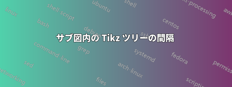
以下のようにサブ図形式で決定木を作成しようとしていますが、どのような間隔を試しても、どこかの時点でノードが重なり合っています。以下の例では、例として同じツリーのコピーを 2 つ持っています。tikz パッケージを使用してこれを修正するにはどうすればよいですか? また、tikz パッケージを使用して少し大きいツリーを描画するためのアドバイスはありますか? うまく機能させるために、レベル/兄弟距離をランダムに変更するだけの段階にいるように感じるので、非常にイライラしています...
\documentclass{book}
\usepackage{tikz}
\usepackage{amsmath,amssymb,amstext,amsthm}
\usepackage{subcaption}
\begin{document}
\begin{figure}
\centering
\begin{subfigure}[h]{0.475\textwidth}
\centering
\begin{tikzpicture}[scale=0.6, level distance=25mm,
    level 1/.style={sibling distance=80mm},
    level 2/.style={sibling distance=50mm},
    level 3/.style={sibling distance=30mm}]
\node[circle, draw]{$x\smash{_1}$}
    child{node[circle, draw]{$x\smash{_2}$}
        child{node[circle, draw]{$x\smash{_4}$}
            child{node[rectangle, draw]{$x\smash{_1} \gets 1$}}
            child{node[rectangle, draw]{$x\smash{_2} \gets 1$}}
        }
        child{node[circle, draw]{$x\smash{_4}$}
            child{node[rectangle, draw]{$x\smash{_1} \gets 1$}}
            child{node[rectangle, draw]{$x\smash{_4} \gets 0$}}
        }
    }
    child{node[circle, draw]{$x\smash{_3}$}
        child{node[circle, draw]{$x\smash{_2}$}
            child{node[rectangle, draw]{$\begin{aligned} x\smash{_1} &\gets 0 \\ x\smash{_3} &\gets 1 \end{aligned}$}}
            child{node[rectangle, draw]{$\begin{aligned} x\smash{_1} &\gets 0 \\ x\smash{_2} &\gets 0 \end{aligned}$}}
        }
        child{node[circle, draw]{$x\smash{_4}$}
            child{node[rectangle, draw]{$x\smash{_4} \gets 1$}}
            child{node[rectangle, draw]{$x\smash{_3} \gets 0$}}
        }
    }
;
\end{tikzpicture}
\caption{A Tree}
\end{subfigure}
\begin{subfigure}[h]{0.475\textwidth}
\centering
\begin{tikzpicture}[scale=0.6, level distance=25mm,
    level 1/.style={sibling distance=80mm},
    level 2/.style={sibling distance=50mm},
    level 3/.style={sibling distance=30mm}]
\node[circle, draw]{$x\smash{_1}$}
    child{node[circle, draw]{$x\smash{_2}$}
        child{node[circle, draw]{$x\smash{_4}$}
            child{node[rectangle, draw]{$x\smash{_1} \gets 1$}}
            child{node[rectangle, draw]{$x\smash{_2} \gets 1$}}
        }
        child{node[circle, draw]{$x\smash{_4}$}
            child{node[rectangle, draw]{$x\smash{_1} \gets 1$}}
            child{node[rectangle, draw]{$x\smash{_4} \gets 0$}}
        }
    }
    child{node[circle, draw]{$x\smash{_3}$}
        child{node[circle, draw]{$x\smash{_2}$}
            child{node[rectangle, draw]{$\begin{aligned} x\smash{_1} &\gets 0 \\ x\smash{_3} &\gets 1 \end{aligned}$}}
            child{node[rectangle, draw]{$\begin{aligned} x\smash{_1} &\gets 0 \\ x\smash{_2} &\gets 0 \end{aligned}$}}
        }
        child{node[circle, draw]{$x\smash{_4}$}
            child{node[rectangle, draw]{$x\smash{_4} \gets 1$}}
            child{node[rectangle, draw]{$x\smash{_3} \gets 0$}}
        }
    }
;
\end{tikzpicture}
\caption{B Tree}
\end{subfigure}
\caption{Caption}
\label{datftt}
\end{figure}
\end{document}
答え1
最終的には、リーフ (エンド) ノード内のテキストから生じるツリーの最小幅があります。両方のツリーで、x_n <- 1エンド ツー エンドの結果をすべて配置すると、すでにテキスト幅の半分以上を占めていることがわかります。これらのツリーを強制的に並べて配置する場合は、ツリーが重なり合うか (現在のように)、ノードが重なり合うかのいずれかになります。どちらのオプションもエレガントではありません...
この最小幅は、下位レベルのフォント サイズを小さくすることで若干調整でき、並べて配置したときに占めるスペースが少なくなります。これは、 で実現できますlevel n/.style={font=\footnotesize}。
また、兄弟間の距離を調整するために試行錯誤を繰り返す必要があるとも述べています。その理由は、Tiの標準的なツリー構築アルゴリズムがけZ には先見性がほとんどありません。次のレベルにnノードがあることを認識し、兄弟間の距離に応じて配置しますが、これらのノードの下にさらに多くのノードがあり、ノードの有効な「幅」が大きくなるかどうかはわかりません。
graph drawingこれはTiのライブラリを使用することで修正できます。けZ. ノードを自動的に配置するアルゴリズムがさらに多く提供され、描画が簡単になります。グラフ
はるかに簡単です。グラフ描画ライブラリの使用方法を示す例を以下に示します。
\documentclass{book}
\usepackage{tikz}
\usetikzlibrary{
  graphs,
  graphdrawing,
}
\usegdlibrary{trees}
\usepackage{amsmath,amssymb,amstext,amsthm}
\usepackage{subcaption}
\begin{document}
\begin{figure}
  \centering
  \begin{subfigure}[b]{\linewidth}
    \centering
    \tikz \graph [
      tree layout,
      nodes={
        draw,
        circle,
      },
      level 3/.style={
        font=\small,
      },
      level 4/.style={
        nodes={
          rectangle,
          font=\footnotesize,
        }
      }
    ] {
      "\(x_{}\)"
        -> {
          "\(x_{1}\)"
          -> {
            "\(x_{11}\)"
            -> {
              "\(x_{111}\)",
              "\(x_{112}\)"
            },
            "\(x_{12}\)"
            -> {
              "\(x_{121}\)",
              "\(x_{122}\)"
            }
          },
          "\(x_{2}\)"
          -> {
            "\(x_{21}\)"
            -> {
              "\(x_{211}\)",
              "\(x_{212}\)"
            },
            "\(x_{22}\)"
            -> {
              "\(x_{221}\)",
              "\(x_{222}\)"
            }
          }
        }
    };
    \caption{Tree \(x\)}
  \end{subfigure}

  \begin{subfigure}[b]{\linewidth}
    \centering
    \tikz \graph [
      tree layout,
      nodes={
        draw,
        circle,
      },
      level 3/.style={
        font=\small,
      },
      level 4/.style={
        nodes={
          rectangle,
          font=\footnotesize,
        }
      }
    ] {
      "\(y_{}\)"
        -> {
          "\(y_{1}\)"
          -> {
            "\(y_{11}\)"
            -> {
              "\(y_{111}\)",
              "\(y_{112}\)"
            },
            "\(y_{12}\)"
            -> {
              "\(y_{121}\)",
              "\(y_{122}\)"
            }
          },
          "\(y_{2}\)"
          -> {
            "\(y_{21}\)"
            -> {
              "\(y_{211}\)",
              "\(y_{212}\)"
            },
            "\(y_{22}\)"
            -> {
              "\(y_{221}\)",
              "\(y_{222}\)"
            }
          }
        }
    };
    \caption{Tree \(y\)}
  \end{subfigure}
  \caption{My awesome captions for trees!}
  \label{fig:trees}
\end{figure}
\end{document}
出力は次のようになります。
