


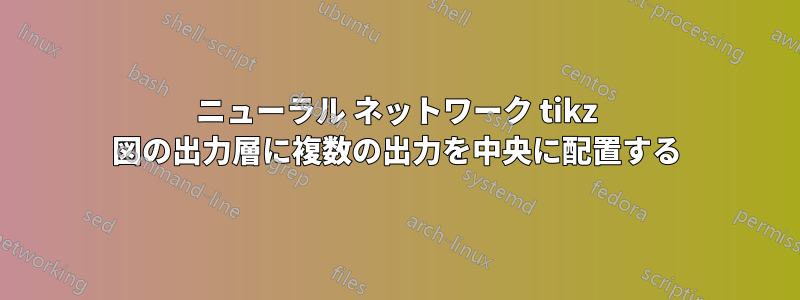
この質問は投稿された解決策の構築ですここ下記のコードは、出力レイヤーが図の残りの部分の中央に配置されていないため、最適化する必要があります。
出力レイヤーを図の残りの部分と中央に配置する方法を知りたいです。
また、現在のようにハードコードするのではなく、出力レイヤーの正しい位置を設定する方法を知りたいと思いました。
\node[output neuron, pin=right:Output \#\y] (O-\name) at (4*\layersep,-\y) {};

これまでに作成したコードは次のとおりです。
\documentclass{article}
\usepackage{tikz}

\begin{document}
\pagestyle{empty}

\def\layersep{2.5cm}

\begin{tikzpicture}[
   shorten >=1pt,->,
   draw=black!50,
    node distance=\layersep,
    every pin edge/.style={<-,shorten <=1pt},
    neuron/.style={circle,fill=black!25,minimum size=17pt,inner sep=0pt},
    input neuron/.style={neuron, fill=green!50},
    output neuron/.style={neuron, fill=red!50},
    hidden neuron/.style={neuron, fill=blue!50},
    annot/.style={text width=4em, text centered}
]

% Draw the input layer nodes
\foreach \name / \y in {1,...,8}
% This is the same as writing \foreach \name / \y in {1/1,2/2,3/3,4/4}
    \node[input neuron, pin=left:Input \#\y] (I-\name) at (0,-\y) {};

% set number of hidden layers
\newcommand\Nhidden{3}

% Draw the hidden layer nodes
\foreach \N in {1,...,\Nhidden} {
   \foreach \y in {1,...,9} {
      \path[yshift=0.5cm]
          node[hidden neuron] (H\N-\y) at (\N*\layersep,-\y cm) {};
       }
\node[annot,above of=H\N-1, node distance=1cm] (hl\N) {Hidden layer \N};
}

% Draw the output layer node
\foreach \name / \y in {1,...,4}
% This is the same as writing \foreach \name / \y in {1/1,2/2,3/3,4/4}
    \node[output neuron, pin=right:Output \#\y] (O-\name) at (4*\layersep,-\y) {};
    %  How to calculate the exact location of the output layers instead of hardcoding the value

% Connect every node in the input layer with every node in the
% hidden layer.
\foreach \source in {1,...,8}
    \foreach \dest in {1,...,9}
        \path (I-\source) edge (H1-\dest);

% connect all hidden stuff
\foreach [remember=\N as \lastN (initially 1)] \N in {2,...,\Nhidden}
   \foreach \source in {1,...,9}
       \foreach \dest in {1,...,9}
           \path (H\lastN-\source) edge (H\N-\dest);

% Connect every node in the hidden layer with the output layer
\foreach [remember=\N as \lastN (initially 3)] \N in {2,...,\Nhidden}
\foreach \source in {1,...,9}
    \foreach \dest in {1,...,4}
        \path (H\lastN-\source) edge (O-\dest);

% Annotate the layers

\node[annot,left of=hl1] {Input layer};
\node[annot,right of=hl\Nhidden] {Output layer};
\end{tikzpicture}
% End of code
\end{document}
答え1
出力層のノードの座標を から に変更し(4*\layersep,-\y)ます(4*\layersep,-\y-2):

MWE を完了する:
\documentclass[tikz, margin=3mm]{standalone}

\begin{document}
\def\layersep{2.5cm}

\begin{tikzpicture}[
   shorten >=1pt,->,
   draw=black!50,
    node distance=\layersep,
    every pin edge/.style={<-,shorten <=1pt},
    neuron/.style={circle,fill=black!25,minimum size=17pt,inner sep=0pt},
    input neuron/.style={neuron, fill=green!50},
    output neuron/.style={neuron, fill=red!50},
    hidden neuron/.style={neuron, fill=blue!50},
    annot/.style={text width=4em, text centered}
]

% Draw the input layer nodes
\foreach \name / \y in {1,...,8}
% This is the same as writing \foreach \name / \y in {1/1,2/2,3/3,4/4}
    \node[input neuron, pin=left:Input \#\y] (I-\name) at (0,-\y) {};

% set number of hidden layers
\newcommand\Nhidden{3}

% Draw the hidden layer nodes
\foreach \N in {1,...,\Nhidden} {
   \foreach \y in {1,...,9} {
      \path[yshift=0.5cm]
          node[hidden neuron] (H\N-\y) at (\N*\layersep,-\y cm) {};
       }
\node[annot,above of=H\N-1, node distance=1cm] (hl\N) {Hidden layer \N};
}

% Draw the output layer node
\foreach \name / \y in {1,...,4}
% This is the same as writing \foreach \name / \y in {1/1,2/2,3/3,4/4}
    \node[output neuron,
          pin=right:Output \#\y] (O-\name)
          at (4*\layersep,-\y-2) {};  % <-----------
    %  How to calculate the exact location of the output layers instead of hardcoding the value

% Connect every node in the input layer with every node in the
% hidden layer.
\foreach \source in {1,...,8}
    \foreach \dest in {1,...,9}
        \path (I-\source) edge (H1-\dest);

% connect all hidden stuff
\foreach [remember=\N as \lastN (initially 1)] \N in {2,...,\Nhidden}
   \foreach \source in {1,...,9}
       \foreach \dest in {1,...,9}
           \path (H\lastN-\source) edge (H\N-\dest);

% Connect every node in the hidden layer with the output layer
\foreach [remember=\N as \lastN (initially 3)] \N in {2,...,\Nhidden}
\foreach \source in {1,...,9}
    \foreach \dest in {1,...,4}
        \path (H\lastN-\source) edge (O-\dest);

% Annotate the layers

\node[annot,left of=hl1] {Input layer};
\node[annot,right of=hl\Nhidden] {Output layer};
\end{tikzpicture}
\end{document}
答え2
他の値はすべてハードコードされているため、ハードコードされていない回答を出すのは難しいです。
at (4*\layersep,{-\y*1cm-(9-4-1)*0.5cm})
なぜなら、層ごとに 9 つの隠しノード、4 つの出力ノードがあり、[yshift=0.5cm]隠しニューロンの構築にハードコードされているため、 が追加されるから-1です。つまり、出力ノードの数を から別の値に変更する場合は、上記の式の を同じ値に4変更する必要があります。4
\documentclass{article}

\usepackage{tikz}
\begin{document}
\pagestyle{empty}

\def\layersep{2.5cm}

\begin{tikzpicture}[
   shorten >=1pt,->,
   draw=black!50,
    node distance=\layersep,
    every pin edge/.style={<-,shorten <=1pt},
    neuron/.style={circle,fill=black!25,minimum size=17pt,inner sep=0pt},
    input neuron/.style={neuron, fill=green!50},
    output neuron/.style={neuron, fill=red!50},
    hidden neuron/.style={neuron, fill=blue!50},
    annot/.style={text width=4em, text centered}
]

% Draw the input layer nodes
\foreach \name / \y in {1,...,8}
% This is the same as writing \foreach \name / \y in {1/1,2/2,3/3,4/4}
    \node[input neuron, pin=left:Input \#\y] (I-\name) at (0,-\y) {};

% set number of hidden layers
\newcommand\Nhidden{3}

% Draw the hidden layer nodes
\foreach \N in {1,...,\Nhidden} {
   \foreach \y in {1,...,9} {
      \path[yshift=0.5cm]
          node[hidden neuron] (H\N-\y) at (\N*\layersep,-\y*1cm) {};
       }
\node[annot,above of=H\N-1, node distance=1cm] (hl\N) {Hidden layer \N};
}

% Draw the output layer node
\foreach \name / \y in {1,...,4}
% This is the same as writing \foreach \name / \y in {1/1,2/2,3/3,4/4}
    \node[output neuron, pin=right:Output \#\y] (O-\name)
    at (4*\layersep,{-\y*1cm-(9-4-1)*0.5cm}) {};
    %  How to calculate the exact location of the output layers instead of hardcoding the value

% Connect every node in the input layer with every node in the
% hidden layer.
\foreach \source in {1,...,8}
    \foreach \dest in {1,...,9}
        \path (I-\source) edge (H1-\dest);

% connect all hidden stuff
\foreach [remember=\N as \lastN (initially 1)] \N in {2,...,\Nhidden}
   \foreach \source in {1,...,9}
       \foreach \dest in {1,...,9}
           \path (H\lastN-\source) edge (H\N-\dest);

% Connect every node in the hidden layer with the output layer
\foreach [remember=\N as \lastN (initially 3)] \N in {2,...,\Nhidden}
\foreach \source in {1,...,9}
    \foreach \dest in {1,...,4}
        \path (H\lastN-\source) edge (O-\dest);

% Annotate the layers

\node[annot,left of=hl1] {Input layer};
\node[annot,right of=hl\Nhidden] {Output layer};
\end{tikzpicture}
\end{document}
