


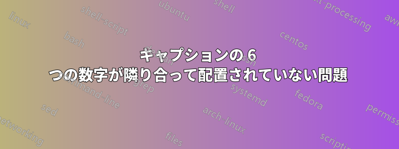
次の TikZ 図のキャプションの配置と全体的な美観を向上させるにはどうすればよいでしょうか?
\documentclass[border=3pt,tikz]{report}
\usepackage{tikz}
\usepackage{float}
\usepackage{caption}
\usetikzlibrary{arrows.meta} % for arrow size
\tikzset{>=latex}
\begin{figure}[H]
        \begin{minipage}{0.16\linewidth}
            % BLOCK - NORMAL (Unloaded)
            \begin{tikzpicture}[x={(0.72cm,-0.08cm)},y={(0.40cm,0.30cm)},z={(0,1cm)}]
            \colorlet{metalcol}{blue!25!black!20!white}
            \tikzstyle{metal}=[draw=metalcol!30!black,rounded corners=0.1,top color=metalcol,bottom color=metalcol!80!black,shading angle=10]
            \tikzstyle{force}=[->,red!65!black]
            \def\W{0.7}     % side width
            \def\H{1.6}     % total height
            \def\F{0.28*\H} % force magnitude
              \draw[metal]
                (0,0,0) --++ (\W,0,0) --++ (0,0,\H) --++ (-\W,0,0) -- cycle
                (\W,0,0) --++ (0,\W,0) --++ (0,0,\H) --++ (0,-\W,0) -- cycle
                (0,0,\H) --++ (\W,0,0) --++ (0,\W,0) --++ (-\W,0,0) -- cycle;
            \end{tikzpicture}
            \caption*{Unloaded}
        \end{minipage}%
        \hfill% not: "\hspace{0.5cm}"
        \begin{minipage}{0.16\linewidth}
            % BLOCK - TENSION
            \begin{tikzpicture}[x={(0.72cm,-0.08cm)},y={(0.40cm,0.30cm)},z={(0,1cm)}]
            \colorlet{metalcol}{blue!25!black!20!white}
            \tikzstyle{metal}=[draw=metalcol!30!black,rounded corners=0.1,top color=metalcol,bottom color=metalcol!80!black,shading angle=10]
            \tikzstyle{force}=[->,red!65!black]
            \def\W{0.7}     % side width
            \def\H{1.6}     % total height
            \def\F{0.28*\H} % force magnitude
              \def\h{1.12*\H}
              \draw[force] (\W/2,\W/2,0) --++ (0,0,-\F);
              \node[below=0pt,left=0pt] at (-3.3,7.5) {$\vec{\sigma}$};
              \node[below=0pt,left=0pt] at (1.6,-1.4) {$\vec{\sigma}$};
              \draw[metal,top color=metalcol!80!blue,bottom color=metalcol!80!blue!80!black]
                (0,0,0) --++ (\W,0,0) to[out=92,in=-92]++ (0,0,\h) --++ (-\W,0,0) to[out=-84,in=84] cycle
                (\W,0,0) --++ (0,\W,0) to[out=96,in=-96]++ (0,0,\h) --++ (0,-\W,0) to[out=-92,in=92] cycle
                (0,0,\h) --++ (\W,0,0) --++ (0,\W,0) --++ (-\W,0,0) -- cycle;
              \draw[force] (\W/2,\W/2,\h) --++ (0,0,\F);
            \end{tikzpicture}
            \caption*{Tension}
        \end{minipage}%
        \hfill% not: "\hspace{0.5cm}"
        \begin{minipage}{0.16\linewidth}
            % BLOCK - COMPRESSION
            \begin{tikzpicture}[x={(0.72cm,-0.08cm)},y={(0.40cm,0.30cm)},z={(0,1cm)}]
            \colorlet{metalcol}{blue!25!black!20!white}
            \tikzstyle{metal}=[draw=metalcol!30!black,rounded corners=0.1,top color=metalcol,bottom color=metalcol!80!black,shading angle=10]
            \tikzstyle{force}=[->,red!65!black]
            \def\W{0.7}     % side width
            \def\H{1.6}     % total height
            \def\F{0.28*\H} % force magnitude
              \def\h{0.88*\H}
              \draw[force] (\W/2,\W/2,-\F) --++ (0,0,\F);
              \node[below=0pt,left=0pt] at (-2.7,6.4) {$\vec{\sigma}$};
              \node[below=0pt,left=0pt] at (1.6,-1.4) {$\vec{\sigma}$};
              \draw[metal,top color=metalcol!78!red,bottom color=metalcol!78!red!80!black]
                (0,0,0) --++ (\W,0,0) to[out=85,in=-85]++ (0,0,\h) --++ (-\W,0,0) to[out=-99,in=99] cycle
                (\W,0,0) --++ (0,\W,0) to[out=81,in=-81]++ (0,0,\h) --++ (0,-\W,0) to[out=-85,in=85] cycle
                (0,0,\h) --++ (\W,0,0) --++ (0,\W,0) --++ (-\W,0,0) -- cycle;
              \draw[force] (\W/2,\W/2,\h+\F) --++ (0,0,-\F);
            \end{tikzpicture}
            \caption*{Compression}
        \end{minipage}
        \hfill% not: "\hspace{0.5cm}"
        \begin{minipage}{0.16\linewidth}
            % BLOCK - BENDING (flexion)
            \begin{tikzpicture}[x={(0.72cm,-0.08cm)},y={(0.40cm,0.30cm)},z={(0,1cm)}]
            \colorlet{metalcol}{blue!25!black!20!white}
            \tikzstyle{metal}=[draw=metalcol!30!black,rounded corners=0.1,top color=metalcol,bottom color=metalcol!80!black,shading angle=10]
            \tikzstyle{force}=[->,red!65!black]
            \def\W{0.7}     % side width
            \def\H{1.6}     % total height
            \def\F{0.28*\H} % force magnitude
              \def\F{0.38*\H} % force magnitude
              \def\dh{0.02*\H}
              \draw[force] (0,0.3*\W,0.85*\H) --++ (-\F,0,-0.25*\F);
              \node[below=0pt,left=0pt] at (-2.7,4.8) {$\vec{M}$};
              \draw[force] (0,0.4*\W,0.13*\H) --++ (-\F,0, 0.10*\F);
              \node[below=0pt,left=0pt] at (-0.2,0.3) {$\vec{M}$};
              \draw[metal,top color=metalcol!70!orange,bottom color=metalcol!70!orange!80!black]
                (0,0,\dh) -- (\W,0,-\dh) to[out=80,in=-80] (\W,0,\H+\dh) -- (0,0,\H-\dh) to[out=-80,in=80] cycle
                (\W,0,-\dh) -- (\W,\W,-\dh) to[out=80,in=-80] (\W,\W,\H+\dh) -- (\W,0,\H+\dh) to[out=-80,in=80] cycle
                (0,0,\H-\dh) -- (\W,0,\H+\dh) -- (\W,\W,\H+\dh) -- (0,\W,\H-\dh) -- cycle;
            \end{tikzpicture}
            \caption*{Bending}
        \end{minipage}
        \hfill% not: "\hspace{0.5cm}"
        \begin{minipage}{0.16\linewidth}
            % BLOCK - TORSION
            \begin{tikzpicture}[x={(0.72cm,-0.08cm)},y={(0.40cm,0.30cm)},z={(0,1cm)}]
            \colorlet{metalcol}{blue!25!black!20!white}
            \tikzstyle{metal}=[draw=metalcol!30!black,rounded corners=0.1,top color=metalcol,bottom color=metalcol!80!black,shading angle=10]
            \tikzstyle{force}=[->,red!65!black]
            \def\W{0.7}     % side width
            \def\H{1.6}     % total height
            \def\F{0.28*\H} % force magnitude
              \def\F{0.41*\H} % force magnitude
              \draw[force] (0,0.04*\W,0.02*\H) --++ (-\F, 0.2*\F,0);
              \node[below=0pt,left=0pt] at (-0.6,0.4) {$\vec{\tau}$};
              \draw[force] (0,0.96*\W,0.98*\H) --++ (-\F,-0.2*\F,0);
              \node[below=0pt,left=0pt] at (-3,4.8) {$\vec{\tau}$};
              \draw[metal,top color=metalcol!80!green,bottom color=metalcol!80!green!80!black]
                (\W,0,0) --++ (0,\W,0) to[out=92,in=-92]++ (-\W,0,\H) -- cycle;
              \draw[metal,top color=metalcol!80!green,bottom color=metalcol!80!green!80!black]
                (0,\W,0) to[out=92,in=-92]++ (0,-\W,\H) --++ (\W,0,0) to[out=-92,in=90] cycle;
              \draw[metal,top color=metalcol!80!green,bottom color=metalcol!80!green!80!black]
                (0,0,0) --++ (\W,0,0) to[out=92,in=-92]++ (0,\W,\H) --++ (0,-\W,0) to[out=-92,in=92] cycle
                (0,0,\H) --++ (\W,0,0) --++ (0,\W,0) --++ (-\W,0,0) -- cycle;
              \draw[force] (1.02*\W,0.10*\W,0.98*\H) --++ (\F, 0.2*\F,0);
              \node[below=0pt,left=0pt] at (-0.6,4.8) {$\vec{\tau}$};
              \draw[force] (1.02*\W,0.90*\W,0.02*\H) --++ (\F,-0.2*\F,0);
              \node[below=0pt,left=0pt] at (1.61,1) {$\vec{\tau}$};
            \end{tikzpicture}
            \caption*{Torsion}
        \end{minipage}
        \hfill% not: "\hspace{0.5cm}"
        \begin{minipage}{0.16\linewidth}
            % BLOCK - SHEAR
            \begin{tikzpicture}[x={(0.72cm,-0.08cm)},y={(0.40cm,0.30cm)},z={(0,1cm)}]
            \colorlet{metalcol}{blue!25!black!20!white}
            \tikzstyle{metal}=[draw=metalcol!30!black,rounded corners=0.1,top color=metalcol,bottom color=metalcol!80!black,shading angle=10]
            \tikzstyle{force}=[->,red!65!black]
            \def\W{0.7}     % side width
            \def\H{1.6}     % total height
            \def\F{0.28*\H} % force magnitude
              \def\dw{\W}
              \def\F{0.38*\H} % force magnitude
              \draw[force] (0,\W/2,0.01*\H) --++ (-\F,0,0);
              \node[below=0pt,left=0pt] at (-0.2,5.3) {$\vec{\tau}$};
              \draw[metal,top color=metalcol!78!purple,bottom color=metalcol!78!purple!80!black]
                (0,0,0) --++ (\W,0,0) --++ (\dw,0,\H) --++ (-\W,0,0) -- cycle
                (\W,0,0) --++ (0,\W,0) --++ (\dw,0,\H) --++ (0,-\W,0) -- cycle
                (\dw,0,\H) --++ (\W,0,0) --++ (0,\W,0) --++ (-\W,0,0) -- cycle;
              \draw[force] (\W+\dw,\W/2,0.98*\H) --++ (\F,0,0);
              \node[below=0pt,left=0pt] at (-0.6,0.4) {$\vec{\tau}$};
            \end{tikzpicture}
            \caption*{Shear}
        \end{minipage}
        \vspace*{3mm}
        \caption{Most common types of material deformations}
    \end{figure}
\end{document}
このコードは実際には次のような醜い結果をもたらします。

答え1
egreg のソリューションは非常にエレガントだと思いますが、私のソリューションはすでに完成しているので、それも投稿します。これは、1 つの TikZ 環境のみを使用し、各ブロックをスコープに配置するため、座標を大量に調整する必要がありませんでした。さらに、スコープを の 1/6 だけシフトすることで幅を推測しました。与えられた MWE では、これは (tikzpicture をスケーリングせずに) オーバーフル hbox につながりますが、MWE 自体にオーバーフル hbox があるため、実際にはスケーリングなしでこれが機能する\textwidthと推測しています。textwidth
\documentclass[border=3pt,tikz]{report}
\usepackage{tikz}
\usepackage{float}
\usepackage{caption}
\usetikzlibrary{arrows.meta} % for arrow size
\tikzset{>=latex}

\begin{document}

\begin{figure}[H]
    \colorlet{metalcol}{blue!25!black!20!white}
    \tikzstyle{metal}=[draw=metalcol!30!black,rounded corners=0.1,top color=metalcol,bottom color=metalcol!80!black,shading angle=10]
    \tikzstyle{force}=[->,red!65!black]
    \def\W{0.7}     % side width
    \def\H{1.6}     % total height
    \def\F{0.28*\H} % force magnitude

    \begin{tikzpicture}[scale=0.96,x={(0.72cm,-0.08cm)},y={(0.40cm,0.30cm)},z={(0,1cm)}]
        % BLOCK - NORMAL (Unloaded)
        \draw[metal]
                (0,0,0) --++ (\W,0,0) --++ (0,0,\H) --++ (-\W,0,0) -- cycle
                (\W,0,0) --++ (0,\W,0) --++ (0,0,\H) --++ (0,-\W,0) -- cycle
                (0,0,\H) --++ (\W,0,0) --++ (0,\W,0) --++ (-\W,0,0) -- cycle;

        \node[anchor=center] at (\W/2,\W/2,-1.2){Unloaded\vphantom{p}};


        % BLOCK - TENSION
        \begin{scope}[xshift=1/6*\textwidth]
                \def\h{1.12*\H}
                \draw[force] (\W/2,\W/2,0) --++ (0,0,-\F);
                \node[below=0pt,left=0pt] at (-3.3,7.5) {$\vec{\sigma}$};
            \node[below=0pt,left=0pt] at (1.6,-1.4) {$\vec{\sigma}$};
            \draw[metal,top color=metalcol!80!blue,bottom color=metalcol!80!blue!80!black]
                (0,0,0) --++ (\W,0,0) to[out=92,in=-92]++ (0,0,\h) --++ (-\W,0,0) to[out=-84,in=84] cycle
                    (\W,0,0) --++ (0,\W,0) to[out=96,in=-96]++ (0,0,\h) --++ (0,-\W,0) to[out=-92,in=92] cycle
                    (0,0,\h) --++ (\W,0,0) --++ (0,\W,0) --++ (-\W,0,0) -- cycle;
            \draw[force] (\W/2,\W/2,\h) --++ (0,0,\F);

            \node[anchor=center] at (\W/2,\W/2,-1.2){Tension\vphantom{p}};
        \end{scope}


        % BLOCK - COMPRESSION
        \begin{scope}[xshift=2/6*\textwidth]
            \def\h{0.88*\H}
                \draw[force] (\W/2,\W/2,-\F) --++ (0,0,\F);
                \node[below=0pt,left=0pt] at (-2.7,6.4) {$\vec{\sigma}$};
                \node[below=0pt,left=0pt] at (1.6,-1.4) {$\vec{\sigma}$};
                \draw[metal,top color=metalcol!78!red,bottom color=metalcol!78!red!80!black]
                    (0,0,0) --++ (\W,0,0) to[out=85,in=-85]++ (0,0,\h) --++ (-\W,0,0) to[out=-99,in=99] cycle
                    (\W,0,0) --++ (0,\W,0) to[out=81,in=-81]++ (0,0,\h) --++ (0,-\W,0) to[out=-85,in=85] cycle
                    (0,0,\h) --++ (\W,0,0) --++ (0,\W,0) --++ (-\W,0,0) -- cycle;
            \draw[force] (\W/2,\W/2,\h+\F) --++ (0,0,-\F);

            \node[anchor=center] at (\W/2,\W/2,-1.2){Compression};
        \end{scope}


        % BLOCK - BENDING (flexion)
        \begin{scope}[xshift=3/6*\textwidth]
            \def\F{0.38*\H} % force magnitude
                \def\dh{0.02*\H}
                \draw[force] (0,0.3*\W,0.85*\H) --++ (-\F,0,-0.25*\F);
                \node[below=0pt,left=0pt] at (-2.7,4.8) {$\vec{M}$};
                \draw[force] (0,0.4*\W,0.13*\H) --++ (-\F,0, 0.10*\F);
            \node[below=0pt,left=0pt] at (-0.2,0.3) {$\vec{M}$};
            \draw[metal,top color=metalcol!70!orange,bottom color=metalcol!70!orange!80!black]
                    (0,0,\dh) -- (\W,0,-\dh) to[out=80,in=-80] (\W,0,\H+\dh) -- (0,0,\H-\dh) to[out=-80,in=80] cycle
                    (\W,0,-\dh) -- (\W,\W,-\dh) to[out=80,in=-80] (\W,\W,\H+\dh) -- (\W,0,\H+\dh) to[out=-80,in=80] cycle
                    (0,0,\H-\dh) -- (\W,0,\H+\dh) -- (\W,\W,\H+\dh) -- (0,\W,\H-\dh) -- cycle;

            \node[anchor=center] at (\W/2,\W/2,-1.2){Bending};
        \end{scope}


        % BLOCK - TORSION
        \begin{scope}[xshift=4/6*\textwidth]
            \def\F{0.41*\H} % force magnitude
            \draw[force] (0,0.04*\W,0.02*\H) --++ (-\F, 0.2*\F,0);
                \node[below=0pt,left=0pt] at (-0.6,0.4) {$\vec{\tau}$};
            \draw[force] (0,0.96*\W,0.98*\H) --++ (-\F,-0.2*\F,0);
            \node[below=0pt,left=0pt] at (-3,4.8) {$\vec{\tau}$};
            \draw[metal,top color=metalcol!80!green,bottom color=metalcol!80!green!80!black]
                    (\W,0,0) --++ (0,\W,0) to[out=92,in=-92]++ (-\W,0,\H) -- cycle;
            \draw[metal,top color=metalcol!80!green,bottom color=metalcol!80!green!80!black]
                    (0,\W,0) to[out=92,in=-92]++ (0,-\W,\H) --++ (\W,0,0) to[out=-92,in=90] cycle;
                \draw[metal,top color=metalcol!80!green,bottom color=metalcol!80!green!80!black]
                (0,0,0) --++ (\W,0,0) to[out=92,in=-92]++ (0,\W,\H) --++ (0,-\W,0) to[out=-92,in=92] cycle
                (0,0,\H) --++ (\W,0,0) --++ (0,\W,0) --++ (-\W,0,0) -- cycle;
                \draw[force] (1.02*\W,0.10*\W,0.98*\H) --++ (\F, 0.2*\F,0);
                \node[below=0pt,left=0pt] at (-0.6,4.8) {$\vec{\tau}$};
                \draw[force] (1.02*\W,0.90*\W,0.02*\H) --++ (\F,-0.2*\F,0);
            \node[below=0pt,left=0pt] at (1.61,1) {$\vec{\tau}$};

            \node[anchor=center] at (\W/2,\W/2,-1.2){Torsion\vphantom{p}};
        \end{scope}


        % BLOCK - SHEAR
        \begin{scope}[xshift=5/6*\textwidth]
            \def\dw{\W}
            \def\F{0.38*\H} % force magnitude
            \draw[force] (0,\W/2,0.01*\H) --++ (-\F,0,0);
                \node[below=0pt,left=0pt] at (-0.2,5.3) {$\vec{\tau}$};
            \draw[metal,top color=metalcol!78!purple,bottom color=metalcol!78!purple!80!black]
                    (0,0,0) --++ (\W,0,0) --++ (\dw,0,\H) --++ (-\W,0,0) -- cycle
                    (\W,0,0) --++ (0,\W,0) --++ (\dw,0,\H) --++ (0,-\W,0) -- cycle
                    (\dw,0,\H) --++ (\W,0,0) --++ (0,\W,0) --++ (-\W,0,0) -- cycle;
                \draw[force] (\W+\dw,\W/2,0.98*\H) --++ (\F,0,0);
                \node[below=0pt,left=0pt] at (-0.6,0.4) {$\vec{\tau}$};

            \node[anchor=center] at (\W/2+\dw/2,\W/2,-1.2){Shear\vphantom{p}};
        \end{scope}
    \end{tikzpicture}

    \caption{Most common types of material deformations}
    \end{figure}
\end{document}
このソリューションはおそらくあまりエレガントではありませんが、ビーム間のスペースを均等に広げるのではなく、ビームを等距離に広げます。
MWE の前後の画像:

答え2
tabular*幅を推測しなくて済むように、外側を使用することをお勧めします。各画像は独自のtabular環境にあるため、垂直に揃えられます。
私はテキスト幅を超えないようにしていました。ドキュメントの実際のテキスト幅に応じて、使用することも、まったく使用しないことも\footnotesizeできます。\small
\tikzstyle数年前に廃止されたことに注意してください。
\documentclass{report}
\usepackage{tikz}

\usetikzlibrary{arrows.meta} % for arrow size
\tikzset{
  >=latex,
  metal/.style={
    draw=metalcol!30!black,
    rounded corners=0.1,
    top color=metalcol,
    bottom color=metalcol!80!black,
    shading angle=10,
  },
  force/.style={->,red!65!black}
}

\begin{document}

\begin{figure}[htp]
\centering\footnotesize
\setlength{\tabcolsep}{0pt}

\begin{tabular*}{\textwidth}{@{\extracolsep{\fill}}cccccc@{}}
  \begin{tabular}{@{}c@{}}
  % BLOCK - NORMAL (Unloaded)
  \begin{tikzpicture}[x={(0.72cm,-0.08cm)},y={(0.40cm,0.30cm)},z={(0,1cm)}]
    \colorlet{metalcol}{blue!25!black!20!white}
    \def\W{0.7}     % side width
    \def\H{1.6}     % total height
    \def\F{0.28*\H} % force magnitude
    \draw[metal]
      (0,0,0) --++ (\W,0,0) --++ (0,0,\H) --++ (-\W,0,0) -- cycle
      (\W,0,0) --++ (0,\W,0) --++ (0,0,\H) --++ (0,-\W,0) -- cycle
      (0,0,\H) --++ (\W,0,0) --++ (0,\W,0) --++ (-\W,0,0) -- cycle;
  \end{tikzpicture}
  \end{tabular}
&
  % BLOCK - TENSION
  \begin{tabular}{@{}c@{}}
  \begin{tikzpicture}[x={(0.72cm,-0.08cm)},y={(0.40cm,0.30cm)},z={(0,1cm)}]
    \colorlet{metalcol}{blue!25!black!20!white}
    \def\W{0.7}     % side width
    \def\H{1.6}     % total height
    \def\F{0.28*\H} % force magnitude
    \def\h{1.12*\H}
    \draw[force] (\W/2,\W/2,0) --++ (0,0,-\F);
    \node[below=0pt,left=0pt] at (-3.3,7.5) {$\vec{\sigma}$};
    \node[below=0pt,left=0pt] at (1.6,-1.4) {$\vec{\sigma}$};
    \draw[metal,top color=metalcol!80!blue,bottom color=metalcol!80!blue!80!black]
      (0,0,0) --++ (\W,0,0) to[out=92,in=-92]++ (0,0,\h) --++ (-\W,0,0) to[out=-84,in=84] cycle
      (\W,0,0) --++ (0,\W,0) to[out=96,in=-96]++ (0,0,\h) --++ (0,-\W,0) to[out=-92,in=92] cycle
      (0,0,\h) --++ (\W,0,0) --++ (0,\W,0) --++ (-\W,0,0) -- cycle;
    \draw[force] (\W/2,\W/2,\h) --++ (0,0,\F);
  \end{tikzpicture}
  \end{tabular}
&
  % BLOCK - COMPRESSION
  \begin{tabular}{@{}c@{}}
  \begin{tikzpicture}[x={(0.72cm,-0.08cm)},y={(0.40cm,0.30cm)},z={(0,1cm)}]
    \colorlet{metalcol}{blue!25!black!20!white}
    \def\W{0.7}     % side width
    \def\H{1.6}     % total height
    \def\F{0.28*\H} % force magnitude
    \def\h{0.88*\H}
    \draw[force] (\W/2,\W/2,-\F) --++ (0,0,\F);
    \node[below=0pt,left=0pt] at (-2.7,6.4) {$\vec{\sigma}$};
    \node[below=0pt,left=0pt] at (1.6,-1.4) {$\vec{\sigma}$};
    \draw[metal,top color=metalcol!78!red,bottom color=metalcol!78!red!80!black]
      (0,0,0) --++ (\W,0,0) to[out=85,in=-85]++ (0,0,\h) --++ (-\W,0,0) to[out=-99,in=99] cycle
      (\W,0,0) --++ (0,\W,0) to[out=81,in=-81]++ (0,0,\h) --++ (0,-\W,0) to[out=-85,in=85] cycle
      (0,0,\h) --++ (\W,0,0) --++ (0,\W,0) --++ (-\W,0,0) -- cycle;
    \draw[force] (\W/2,\W/2,\h+\F) --++ (0,0,-\F);
  \end{tikzpicture}
  \end{tabular}
&
  \begin{tabular}{@{}c@{}}
  % BLOCK - BENDING (flexion)
  \begin{tikzpicture}[x={(0.72cm,-0.08cm)},y={(0.40cm,0.30cm)},z={(0,1cm)}]
    \colorlet{metalcol}{blue!25!black!20!white}
    \def\W{0.7}     % side width
    \def\H{1.6}     % total height
    \def\F{0.38*\H} % force magnitude
    \def\dh{0.02*\H}
    \draw[force] (0,0.3*\W,0.85*\H) --++ (-\F,0,-0.25*\F);
    \node[below=0pt,left=0pt] at (-2.7,4.8) {$\vec{M}$};
    \draw[force] (0,0.4*\W,0.13*\H) --++ (-\F,0, 0.10*\F);
    \node[below=0pt,left=0pt] at (-0.2,0.3) {$\vec{M}$};
    \draw[metal,top color=metalcol!70!orange,bottom color=metalcol!70!orange!80!black]
      (0,0,\dh) -- (\W,0,-\dh) to[out=80,in=-80] (\W,0,\H+\dh) -- (0,0,\H-\dh) to[out=-80,in=80] cycle
      (\W,0,-\dh) -- (\W,\W,-\dh) to[out=80,in=-80] (\W,\W,\H+\dh) -- (\W,0,\H+\dh) to[out=-80,in=80] cycle
      (0,0,\H-\dh) -- (\W,0,\H+\dh) -- (\W,\W,\H+\dh) -- (0,\W,\H-\dh) -- cycle;
  \end{tikzpicture}
  \end{tabular}
&
  \begin{tabular}{@{}c@{}}
  % BLOCK - TORSION
  \begin{tikzpicture}[x={(0.72cm,-0.08cm)},y={(0.40cm,0.30cm)},z={(0,1cm)}]
    \colorlet{metalcol}{blue!25!black!20!white}
    \def\W{0.7}     % side width
    \def\H{1.6}     % total height
    \def\F{0.41*\H} % force magnitude
    \draw[force] (0,0.04*\W,0.02*\H) --++ (-\F, 0.2*\F,0);
    \node[below=0pt,left=0pt] at (-0.6,0.4) {$\vec{\tau}$};
    \draw[force] (0,0.96*\W,0.98*\H) --++ (-\F,-0.2*\F,0);
    \node[below=0pt,left=0pt] at (-3,4.8) {$\vec{\tau}$};
    \draw[metal,top color=metalcol!80!green,bottom color=metalcol!80!green!80!black]
      (\W,0,0) --++ (0,\W,0) to[out=92,in=-92]++ (-\W,0,\H) -- cycle;
    \draw[metal,top color=metalcol!80!green,bottom color=metalcol!80!green!80!black]
      (0,\W,0) to[out=92,in=-92]++ (0,-\W,\H) --++ (\W,0,0) to[out=-92,in=90] cycle;
    \draw[metal,top color=metalcol!80!green,bottom color=metalcol!80!green!80!black]
      (0,0,0) --++ (\W,0,0) to[out=92,in=-92]++ (0,\W,\H) --++ (0,-\W,0) to[out=-92,in=92] cycle
      (0,0,\H) --++ (\W,0,0) --++ (0,\W,0) --++ (-\W,0,0) -- cycle;
    \draw[force] (1.02*\W,0.10*\W,0.98*\H) --++ (\F, 0.2*\F,0);
    \node[below=0pt,left=0pt] at (-0.6,4.8) {$\vec{\tau}$};
    \draw[force] (1.02*\W,0.90*\W,0.02*\H) --++ (\F,-0.2*\F,0);
    \node[below=0pt,left=0pt] at (1.61,1) {$\vec{\tau}$};
  \end{tikzpicture}
  \end{tabular}
&
  \begin{tabular}{@{}c@{}}
  % BLOCK - SHEAR
  \begin{tikzpicture}[x={(0.72cm,-0.08cm)},y={(0.40cm,0.30cm)},z={(0,1cm)}]
    \colorlet{metalcol}{blue!25!black!20!white}
    \def\W{0.7}     % side width
    \def\H{1.6}     % total height
    \def\dw{\W}
    \def\F{0.38*\H} % force magnitude
    \draw[force] (0,\W/2,0.01*\H) --++ (-\F,0,0);
    \node[below=0pt,left=0pt] at (-0.2,5.3) {$\vec{\tau}$};
    \draw[metal,top color=metalcol!78!purple,bottom color=metalcol!78!purple!80!black]
      (0,0,0) --++ (\W,0,0) --++ (\dw,0,\H) --++ (-\W,0,0) -- cycle
      (\W,0,0) --++ (0,\W,0) --++ (\dw,0,\H) --++ (0,-\W,0) -- cycle
      (\dw,0,\H) --++ (\W,0,0) --++ (0,\W,0) --++ (-\W,0,0) -- cycle;
    \draw[force] (\W+\dw,\W/2,0.98*\H) --++ (\F,0,0);
    \node[below=0pt,left=0pt] at (-0.6,0.4) {$\vec{\tau}$};
  \end{tikzpicture}
  \end{tabular}
\\
Unloaded & Tension & Compression & Bending & Torsion & Shear
\end{tabular*}

\caption{Most common types of material deformations}

\end{figure}

\end{document}

答え3
最初の一歩subfigure: 図のコードを大幅に短くし、 odパッケージを使用してサブキャプションを垂直に揃えますsubcaption。
\documentclass{report}
\usepackage{subcaption}
\usepackage{tikz}
\usetikzlibrary{arrows.meta} % for arrow size
\colorlet{metalcol}{blue!25!black!20!white}

\begin{document}
    \begin{figure}[ht]
\tikzset{
    >=Straight Barb,
    x={(0.72cm,-0.08cm)},y={(0.40cm,0.30cm)},z={(0,1cm)},
    metal/.style args = {#1/#2}{draw=metalcol!30!black, rounded corners=0.1,
            top color=metalcol!#1, bottom color=metalcol!#2,
            shading angle=10},
    force/.style = {->,red!65!black}
        }
\def\W{0.7}     % side width
\def\H{1.6}     % total height
\def\F{0.28*\H} % force magnitude

\begin{subfigure}[b]{0.16\linewidth}
    \begin{tikzpicture}
%
\draw[metal=1/80!black]  %top color=metalcol,bottom color=metalcol!80!black
    (0,0,0)  --++ (\W,0,0) --++ (0,0,\H) --++ (-\W,0,0) -- cycle
    (\W,0,0) --++ (0,\W,0) --++ (0,0,\H) --++ (0,-\W,0) -- cycle
    (0,0,\H) --++ (\W,0,0) --++ (0,\W,0) --++ (-\W,0,0) -- cycle;
    \end{tikzpicture}
\caption*{Unloaded}
\end{subfigure}%
\hfill
\begin{subfigure}[b]{0.16\linewidth}
    \begin{tikzpicture}
\def\h{1.12*\H}
\draw[force] (\W/2,\W/2,0) --++ (0,0,-\F);
\node[below,left] at (-3.3,7.5) {$\vec{\sigma}$};
\node[below,left] at (1.6,-1.4) {$\vec{\sigma}$};
\draw[metal=80!blue/80!blue!80!black]
    (0,0,0) --++ (\W,0,0) to[out=92,in=-92]++ (0,0,\h) --++ (-\W,0,0) to[out=-84,in=84] cycle
    (\W,0,0) --++ (0,\W,0) to[out=96,in=-96]++ (0,0,\h) --++ (0,-\W,0) to[out=-92,in=92] cycle
    (0,0,\h) --++ (\W,0,0) --++ (0,\W,0) --++ (-\W,0,0) -- cycle;
\draw[force] (\W/2,\W/2,\h) --++ (0,0,\F);
    \end{tikzpicture}
\caption*{Tension}
\end{subfigure}%
\hfill
\begin{subfigure}[b]{0.16\linewidth}
    \begin{tikzpicture}
\def\h{0.88*\H}
\draw[force] (\W/2,\W/2,-\F) --++ (0,0,\F);
\node[below,left] at (-2.7,6.4) {$\vec{\sigma}$};
\node[below,left] at (1.6,-1.4) {$\vec{\sigma}$};
\draw[metal=78!red/78!red!80!black]
    (0,0,0) --++ (\W,0,0) to[out=85,in=-85]++ (0,0,\h) --++ (-\W,0,0) to[out=-99,in=99] cycle
    (\W,0,0) --++ (0,\W,0) to[out=81,in=-81]++ (0,0,\h) --++ (0,-\W,0) to[out=-85,in=85] cycle
    (0,0,\h) --++ (\W,0,0) --++ (0,\W,0) --++ (-\W,0,0) -- cycle;
\draw[force] (\W/2,\W/2,\h+\F) --++ (0,0,-\F);
    \end{tikzpicture}
\caption*{Compression}
\end{subfigure}
\hfill
\begin{subfigure}[b]{0.16\linewidth}
            % BLOCK - BENDING (flexion)
    \begin{tikzpicture}
\def\dh{0.02*\H}
\draw[force] (0,0.3*\W,0.85*\H) --++ (-\F,0,-0.25*\F);
\node[below,left] at (-2.7,4.8) {$\vec{M}$};
\draw[force] (0,0.4*\W,0.13*\H) --++ (-\F,0, 0.10*\F);
\node[below,left] at (-0.2,0.3) {$\vec{M}$};
\draw[metal=70!orange/70!orange!80!black]%top color=metalcol!70!orange,bottom color=metalcol!70!orange!80!black]
    (0,0,\dh) -- (\W,0,-\dh) to[out=80,in=-80] (\W,0,\H+\dh) -- (0,0,\H-\dh) to[out=-80,in=80] cycle
    (\W,0,-\dh) -- (\W,\W,-\dh) to[out=80,in=-80] (\W,\W,\H+\dh) -- (\W,0,\H+\dh) to[out=-80,in=80] cycle
    (0,0,\H-\dh) -- (\W,0,\H+\dh) -- (\W,\W,\H+\dh) -- (0,\W,\H-\dh) -- cycle;
    \end{tikzpicture}
\caption*{Bending}
\end{subfigure}
\hfill
\begin{subfigure}[b]{0.16\linewidth}
            % BLOCK - TORSION
    \begin{tikzpicture}
\def\F{0.41*\H} % force magnitude
\draw[force] (0,0.04*\W,0.02*\H) --++ (-\F, 0.2*\F,0);
\node[below,left] at (-0.6,0.4) {$\vec{\tau}$};
\draw[force] (0,0.96*\W,0.98*\H) --++ (-\F,-0.2*\F,0);
\node[below,left] at (-3,4.8) {$\vec{\tau}$};
\draw[metal=80!green/80!green!80!black]
    (\W,0,0) --++ (0,\W,0) to[out=92,in=-92]++ (-\W,0,\H) -- cycle;
\draw[metal=80!green/80!green!80!black]
    (0,\W,0) to[out=92,in=-92]++ (0,-\W,\H) --++ (\W,0,0) to[out=-92,in=90] cycle;
\draw[metal=80!green/80!green!80!black]%top
    (0,0,0) --++ (\W,0,0) to[out=92,in=-92]++ (0,\W,\H) --++ (0,-\W,0) to[out=-92,in=92] cycle
    (0,0,\H) --++ (\W,0,0) --++ (0,\W,0) --++ (-\W,0,0) -- cycle;
\draw[force] (1.02*\W,0.10*\W,0.98*\H) --++ (\F, 0.2*\F,0);
\node[below,left] at (-0.6,4.8) {$\vec{\tau}$};
\draw[force] (1.02*\W,0.90*\W,0.02*\H) --++ (\F,-0.2*\F,0);
\node[below,left] at (1.61,1) {$\vec{\tau}$};
    \end{tikzpicture}
    \caption*{Torsion}
\end{subfigure}
\hfill
\begin{subfigure}{0.16\linewidth}
            % BLOCK - SHEAR
    \begin{tikzpicture}
\def\dw{\W}
\def\F{0.38*\H} % force magnitude
\draw[force] (0,\W/2,0.01*\H) --++ (-\F,0,0);
\node[below,left] at (-0.2,5.3) {$\vec{\tau}$};
\draw[metal=78!purple/78!purple!80!black]%,top color=metalcol!78!purple,bottom color=metalcol!78!purple!80!black
    (0,0,0) --++ (\W,0,0) --++ (\dw,0,\H) --++ (-\W,0,0) -- cycle
    (\W,0,0) --++ (0,\W,0) --++ (\dw,0,\H) --++ (0,-\W,0) -- cycle
    (\dw,0,\H) --++ (\W,0,0) --++ (0,\W,0) --++ (-\W,0,0) -- cycle;
\draw[force] (\W+\dw,\W/2,0.98*\H) --++ (\F,0,0);
\node[below,left] at (-0.6,0.4) {$\vec{\tau}$};
    \end{tikzpicture}
            \caption*{Shear}
\end{subfigure}
\caption{Most common types of material deformations}
    \end{figure}
\end{document}

第二段階baseline=(current bounding box.center): 画像を垂直方向に揃えて、テーブルtikzpictureに挿入します。この図を使用するtvlrと、コードがさらに短縮されます。おそらく、次のようになります。
\documentclass{report}
\usepackage{tabularray}
\usepackage{tikz}
\usetikzlibrary{arrows.meta} % for arrow size
\colorlet{metalcol}{blue!25!black!20!white}

\begin{document}
    \begin{figure}[ht]
\tikzset{
    >=Straight Barb,
    x={(0.72cm,-0.08cm)},y={(0.40cm,0.30cm)},z={(0,1cm)},
    metal/.style args = {#1/#2}{draw=metalcol!30!black, rounded corners=0.1,
            top color=metalcol!#1, bottom color=metalcol!#2,
            shading angle=10},
    force/.style = {->,red!65!black},
    baseline=(current bounding box.center)
        }
\def\W{0.7}     % side width
\def\H{1.6}     % total height
\def\F{0.28*\H} % force magnitude

    \begin{tblr}{colspec = {@{} *{6}{X[c]} @{}}}
    \begin{tikzpicture}
\draw[metal=1/80!black]
    (0,0,0)  --++ (\W,0,0) --++ (0,0,\H) --++ (-\W,0,0) -- cycle
    (\W,0,0) --++ (0,\W,0) --++ (0,0,\H) --++ (0,-\W,0) -- cycle
    (0,0,\H) --++ (\W,0,0) --++ (0,\W,0) --++ (-\W,0,0) -- cycle;
    \end{tikzpicture}
&
    \begin{tikzpicture}
\def\h{1.12*\H}
\draw[force] (\W/2,\W/2,0) --++ (0,0,-\F);
\node[below,left] at (-3.3,7.5) {$\vec{\sigma}$};
\node[below,left] at (1.6,-1.4) {$\vec{\sigma}$};
\draw[metal=80!blue/80!blue!80!black]
    (0,0,0) --++ (\W,0,0) to[out=92,in=-92]++ (0,0,\h) --++ (-\W,0,0) to[out=-84,in=84] cycle
    (\W,0,0) --++ (0,\W,0) to[out=96,in=-96]++ (0,0,\h) --++ (0,-\W,0) to[out=-92,in=92] cycle
    (0,0,\h) --++ (\W,0,0) --++ (0,\W,0) --++ (-\W,0,0) -- cycle;
\draw[force] (\W/2,\W/2,\h) --++ (0,0,\F);
    \end{tikzpicture}
&
    \begin{tikzpicture}
\def\h{0.88*\H}
\draw[force] (\W/2,\W/2,-\F) --++ (0,0,\F);
\node[below,left] at (-2.7,6.4) {$\vec{\sigma}$};
\node[below,left] at (1.6,-1.4) {$\vec{\sigma}$};
\draw[metal=78!red/78!red!80!black]
    (0,0,0) --++ (\W,0,0) to[out=85,in=-85]++ (0,0,\h) --++ (-\W,0,0) to[out=-99,in=99] cycle
    (\W,0,0) --++ (0,\W,0) to[out=81,in=-81]++ (0,0,\h) --++ (0,-\W,0) to[out=-85,in=85] cycle
    (0,0,\h) --++ (\W,0,0) --++ (0,\W,0) --++ (-\W,0,0) -- cycle;
\draw[force] (\W/2,\W/2,\h+\F) --++ (0,0,-\F);
    \end{tikzpicture}
&
    \begin{tikzpicture}
\def\dh{0.02*\H}
\draw[force] (0,0.3*\W,0.85*\H) --++ (-\F,0,-0.25*\F);
\node[below,left] at (-2.7,4.8) {$\vec{M}$};
\draw[force] (0,0.4*\W,0.13*\H) --++ (-\F,0, 0.10*\F);
\node[below,left] at (-0.2,0.3) {$\vec{M}$};
\draw[metal=70!orange/70!orange!80!black]%top color=metalcol!70!orange,bottom color=metalcol!70!orange!80!black]
    (0,0,\dh) -- (\W,0,-\dh) to[out=80,in=-80] (\W,0,\H+\dh) -- (0,0,\H-\dh) to[out=-80,in=80] cycle
    (\W,0,-\dh) -- (\W,\W,-\dh) to[out=80,in=-80] (\W,\W,\H+\dh) -- (\W,0,\H+\dh) to[out=-80,in=80] cycle
    (0,0,\H-\dh) -- (\W,0,\H+\dh) -- (\W,\W,\H+\dh) -- (0,\W,\H-\dh) -- cycle;
    \end{tikzpicture}
&
    \begin{tikzpicture}
\def\F{0.41*\H} % force magnitude
\draw[force] (0,0.04*\W,0.02*\H) --++ (-\F, 0.2*\F,0);
\node[below,left] at (-0.6,0.4) {$\vec{\tau}$};
\draw[force] (0,0.96*\W,0.98*\H) --++ (-\F,-0.2*\F,0);
\node[below,left] at (-3,4.8) {$\vec{\tau}$};
\draw[metal=80!green/80!green!80!black]
    (\W,0,0) --++ (0,\W,0) to[out=92,in=-92]++ (-\W,0,\H) -- cycle;
\draw[metal=80!green/80!green!80!black]
    (0,\W,0) to[out=92,in=-92]++ (0,-\W,\H) --++ (\W,0,0) to[out=-92,in=90] cycle;
\draw[metal=80!green/80!green!80!black]%top
    (0,0,0) --++ (\W,0,0) to[out=92,in=-92]++ (0,\W,\H) --++ (0,-\W,0) to[out=-92,in=92] cycle
    (0,0,\H) --++ (\W,0,0) --++ (0,\W,0) --++ (-\W,0,0) -- cycle;
\draw[force] (1.02*\W,0.10*\W,0.98*\H) --++ (\F, 0.2*\F,0);
\node[below,left] at (-0.6,4.8) {$\vec{\tau}$};
\draw[force] (1.02*\W,0.90*\W,0.02*\H) --++ (\F,-0.2*\F,0);
\node[below,left] at (1.61,1) {$\vec{\tau}$};
    \end{tikzpicture}
&
    \begin{tikzpicture}
\def\dw{\W}
\def\F{0.38*\H} % force magnitude
\draw[force] (0,\W/2,0.01*\H) --++ (-\F,0,0);
\node[below,left] at (-0.2,5.3) {$\vec{\tau}$};
\draw[metal=78!purple/78!purple!80!black]%,top color=metalcol!78!purple,bottom color=metalcol!78!purple!80!black
    (0,0,0) --++ (\W,0,0) --++ (\dw,0,\H) --++ (-\W,0,0) -- cycle
    (\W,0,0) --++ (0,\W,0) --++ (\dw,0,\H) --++ (0,-\W,0) -- cycle
    (\dw,0,\H) --++ (\W,0,0) --++ (0,\W,0) --++ (-\W,0,0) -- cycle;
\draw[force] (\W+\dw,\W/2,0.98*\H) --++ (\F,0,0);
\node[below=0pt,left=0pt] at (-0.6,0.4) {$\vec{\tau}$};
    \end{tikzpicture}       \\
Unloaded & Tension & Compression & Bending & Torsion & Shear
    \end{tblr}
\caption{Most common types of material deformations}
    \end{figure}
\end{document}

答え4
TikZ マトリックス:
between origins変形したブロックを幅全体に均等に分散します (もちろん、これはブロックの幅がほぼ同じ場合にのみ有効です)。左側(視覚的な中心を中心とする)を右側(視覚的な中心を中心とする)と同じ幅にするトリミング。剪断それに比べると、図は非常に右側に突き出ています。
このため、せん断図のノードは他のノードよりも内側に配置されます。
column sep = 2\tabcolsep環境の水平間隔をシミュレートするには、次のようなものを使用できますtabular。次に、2 行目のノードにセップがないようにして、列内にしっかりと配置することが重要です。
同じ
forceパスを使用していることに注目してください圧縮はどうかと言うとテンションただし、矢印の先端を反転しただけです。パッケージ
geometryはテキスト領域を表示するために使用されます。
コード
\documentclass{report}
\usepackage{tikz}
\usepackage{float}
\usetikzlibrary{arrows.meta, calc} % for arrow size
\tikzset{
  tight matrix/.style={
    matrix, every outer matrix/.append style={
      inner sep=+0pt, outer sep=+0pt, shape=rectangle, path only}},
  material deformations diagrams/.style={
    /utils/exec=%
      \colorlet{metalcol}{blue!25!black!20!white}%
      \def\W{0.7}%     side width
      \def\H{1.6}%     total height
      \def\F{0.28*\H},%force magnitude
    metal/.style={
      rounded corners=0.1, draw=metalcol!30!black, shading angle=10,
      top color=metalcol!##1, bottom color=metalcol!##1!80!black},
    metal/.default=80!black,
    force/.style={>=Latex, ->, draw=red!65!black},
    x={(0.72cm,-0.08cm)}, y={(0.40cm,0.30cm)}, z={(0,1cm)}}}
\usepackage[showframe]{geometry}
\begin{document}
\begin{figure}[H]
\centering
\begin{tikzpicture}[material deformations diagrams,
  % to make the left side as wide as the right side
  % centered around the middle of subfigures
  trim left=($(current bounding box.east)!2!($(n3)!.5!(n4)$)$),
  % this does the same visually but doesn't warn about overfull hboxes:
  % trim left=(n1), trim right=(n6)
]
\matrix[
  tight matrix, row sep=+.7em,
  %
  % I'd suggest between origins for distributing the figures equally
  % for this, we name the nodes and use them
  % to trim the picture so that it is centered
  % we actually subtract a bit from the available width
  % because the Shear picture extrudes very much to the right
  column sep={\linewidth/6,between origins},
  %
  % The middle of the defomred blocks are roughly centered above the text:
  row 1/.append code=\tikzset{shift={(-\W/2,-\W/2)}},
  %
  % anchor = base: for vertical alignment of nodes
  % no seps:       for as tight as possible (when not *between origins*)
  % node names:    for trimming
  row 2/.append style={inner sep=+0pt, outer sep=+0pt, anchor=base,
    nodes={name=n\the\pgfmatrixcurrentcolumn}}]{
\draw[metal, top color=metalcol]
  (0,0,0)  --++ (\W,0,0) --++ (0,0,\H) --++ (-\W,0,0) -- cycle
  (\W,0,0) --++ (0,\W,0) --++ (0,0,\H) --++ (0,-\W,0) -- cycle
  (0,0,\H) --++ (\W,0,0) --++ (0,\W,0) --++ (-\W,0,0) -- cycle;
&
\def\h{1.12*\H}
\draw[force] (\W/2,\W/2,0) --++ (0,0,-\F) node[below]{$\vec{\sigma}$};
\draw[metal=80!blue]
  (0,0,0)  --++ (\W,0,0) to[out=92,in=-92]++ (0,0,\h) --++ (-\W,0,0) to[out=-84,in=84] cycle
  (\W,0,0) --++ (0,\W,0) to[out=96,in=-96]++ (0,0,\h) --++ (0,-\W,0) to[out=-92,in=92] cycle
  (0,0,\h) --++ (\W,0,0) --++ (0,\W,0) --++ (-\W,0,0) -- cycle;
\draw[force] (\W/2,\W/2,\h) --++ (0,0,\F) node[above]{$\vec{\sigma}$};
&
\def\h{0.88*\H}
\draw[force, <-] (\W/2,\W/2,0) --++ (0,0,-\F) node[below]{$\vec{\sigma}$};
\draw[metal=78!red]
  (0,0,0)  --++ (\W,0,0) to[out=85,in=-85]++ (0,0,\h) --++ (-\W,0,0) to[out=-99,in=99] cycle
  (\W,0,0) --++ (0,\W,0) to[out=81,in=-81]++ (0,0,\h) --++ (0,-\W,0) to[out=-85,in=85] cycle
  (0,0,\h) --++ (\W,0,0) --++ (0,\W,0) --++ (-\W,0,0) -- cycle;
\draw[force, <-] (\W/2,\W/2,\h) --++ (0,0,\F) node[above]{$\vec{\sigma}$};
&
\def\F{0.38*\H} % force magnitude
\def\dh{0.02*\H}
\draw[force] (0,0.3*\W,0.85*\H) --++ (-\F,0,-0.25*\F) node[left]{$\vec{M}$};
\draw[force] (0,0.4*\W,0.13*\H) --++ (-\F,0, 0.10*\F) node[left]{$\vec{M}$};
\draw[metal=70!orange]
  (0,0,\dh)    -- (\W,0,-\dh)  to[out=80,in=-80] (\W,0,\H+\dh)  -- (0,0,\H-\dh)  to[out=-80,in=80] cycle
  (\W,0,-\dh)  -- (\W,\W,-\dh) to[out=80,in=-80] (\W,\W,\H+\dh) -- (\W,0,\H+\dh) to[out=-80,in=80] cycle
  (0,0,\H-\dh) -- (\W,0,\H+\dh) -- (\W,\W,\H+\dh) -- (0,\W,\H-\dh) -- cycle;
&
\def\F{0.41*\H} % force magnitude
\draw[force] (0,0.04*\W,0.02*\H) --++ (-\F, 0.2*\F,0) node[left]{$\vec{\tau}$};
\draw[force] (0,0.96*\W,0.98*\H) --++ (-\F,-0.2*\F,0) node[left]{$\vec{\tau}$};
\draw[metal=80!green]
  (\W,0,0) --++ (0,\W,0) to[out=92,in=-92]++ (-\W,0,\H) -- cycle;
\draw[metal=80!green]
  (0,\W,0) to[out=92,in=-92]++ (0,-\W,\H) --++ (\W,0,0) to[out=-92,in=90] cycle;
\draw[metal=80!green]
  (0,0,0) --++ (\W,0,0) to[out=92,in=-92]++ (0,\W,\H) --++ (0,-\W,0) to[out=-92,in=92] cycle
  (0,0,\H) --++ (\W,0,0) --++ (0,\W,0) --++ (-\W,0,0) -- cycle;
\draw[force] (1.02*\W,0.10*\W,0.98*\H) --++ (\F, 0.2*\F,0) node[right]{$\vec{\tau}$};
\draw[force] (1.02*\W,0.90*\W,0.02*\H) --++ (\F,-0.2*\F,0) node[right]{$\vec{\tau}$};
&
\def\dw{\W}
\def\F{0.38*\H} % force magnitude
\draw[force] (0,\W/2,0.01*\H) --++ (-\F,0,0) node[above right]{$\vec{\tau}$};
\draw[metal=78!purple]
  (0,0,0) --++ (\W,0,0) --++ (\dw,0,\H) --++ (-\W,0,0) -- cycle
  (\W,0,0) --++ (0,\W,0) --++ (\dw,0,\H) --++ (0,-\W,0) -- cycle
  (\dw,0,\H) --++ (\W,0,0) --++ (0,\W,0) --++ (-\W,0,0) -- cycle;
\draw[force] (\W+\dw,\W/2,0.98*\H) --++ (\F,0,0) node[below left]{$\vec{\tau}$};
\\
\node{Unloaded}; & \node{Tension}; & \node{Compression}; & \node{Bending}; & \node{Torsion}; & \node{Shear};
\\};
\end{tikzpicture}
\caption{Most common types of material deformations}
\end{figure}
\end{document}
出力
