


%20%E3%82%92%E6%8F%8F%E3%81%8F%E3%81%AB%E3%81%AF%E3%81%A9%E3%81%86%E3%81%99%E3%82%8C%E3%81%B0%E3%82%88%E3%81%84%E3%81%A7%E3%81%97%E3%82%87%E3%81%86%E3%81%8B%3F.png)
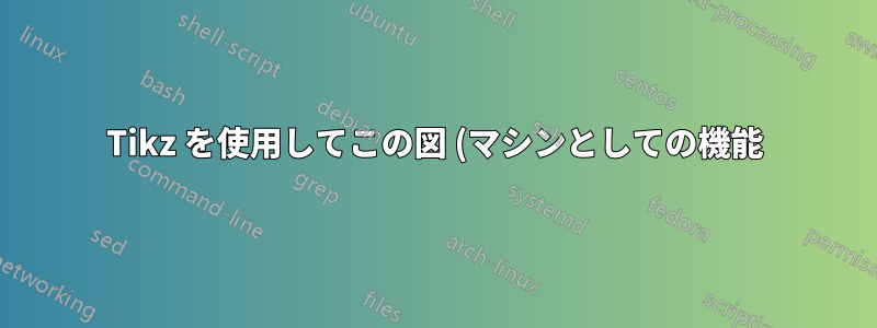
下の図を再現したいのですが、その図形の「コード」が見つかりません。私が見たサンプル図には、閉じた四角形と、その四角形に向かう矢印とそこから出る矢印が描かれているだけです。どなたか助けていただければ幸いです。

添付されているのは、Jasper が提案した現在の MWE です。
\tikzstyle{Box} = [rectangle, rounded corners, minimum width=2cm, minimum height=1.25cm, text centered, draw=blue, inner color=white, outer color=blue!30]
\tikzstyle{arrow} = [red, very thick,->,>=stealth]

\begin{center}
\begin{tikzpicture}[node distance=2.5cm]
\node (A) [Box] {\(f\)};
\node (B) [left of=A, label=below:{input}] {$x$};
\node (C) [right of=A, label=below:{output}] {$y$};
\draw [arrow] (B) -- (A);
\draw [arrow] (A) -- (C);
\end{tikzpicture}
\end{center}
答え1
図形がない場合は、次のように作成できます\pic。
\documentclass[border=10pt]{standalone}
\usepackage{tikz}

\tikzset{
    pics/machine/.style={
        code={
            \coordinate (-in) at ({-0.5*\pgfkeysvalueof{/tikz/machine/width}},0);
            \coordinate (-out) at ({0.5*\pgfkeysvalueof{/tikz/machine/width}},0);
            \coordinate (-north) at (0,{0.5*\pgfkeysvalueof{/tikz/machine/height}});
            \coordinate (-south) at (0,{-0.5*\pgfkeysvalueof{/tikz/machine/height}});
            \path[/tikz/machine/filling]
                ([shift={(-0.75em,0.5em)}]-in)
                -- ([shift={(0,0.25em)}]-in)
                -- ([shift={(0,-5pt)}]-north -| -in)
                arc[start angle=180, end angle=90, radius=5pt]
                -- ([shift={(-5pt,0)}]-north -| -out)
                arc[start angle=90, end angle=0, radius=5pt]
                -- ([shift={(0,0.25em)}]-out)
                -- ([shift={(0.75em,0.5em)}]-out)
                -- ([shift={(0.75em,-0.5em)}]-out)
                -- ([shift={(0,-0.25em)}]-out)
                -- ([shift={(0,5pt)}]-south -| -out)
                arc[start angle=360, end angle=270, radius=5pt]
                -- ([shift={(5pt,0)}]-south -| -in)
                arc[start angle=270, end angle=180, radius=5pt]
                -- ([shift={(0,-0.25em)}]-in)
                -- ([shift={(-0.75em,-0.5em)}]-in)
                -- cycle;
            \draw[/tikz/machine/border]
                ([shift={(-0.75em,0.5em)}]-in)
                -- ([shift={(0,0.25em)}]-in)
                -- ([shift={(0,-5pt)}]-north -| -in)
                arc[start angle=180, end angle=90, radius=5pt]
                -- ([shift={(-5pt,0)}]-north -| -out)
                arc[start angle=90, end angle=0, radius=5pt]
                -- ([shift={(0,0.25em)}]-out)
                -- ([shift={(0.75em,0.5em)}]-out);
            \draw[/tikz/machine/border]
                ([shift={(0.75em,-0.5em)}]-out)
                -- ([shift={(0,-0.25em)}]-out)
                -- ([shift={(0,5pt)}]-south -| -out)
                arc[start angle=360, end angle=270, radius=5pt]
                -- ([shift={(5pt,0)}]-south -| -in)
                arc[start angle=270, end angle=180, radius=5pt]
                -- ([shift={(0,-0.25em)}]-in)
                -- ([shift={(-0.75em,-0.5em)}]-in);
            \node (-node) at (0,0) {#1};
        }
    },
    machine/width/.initial={3.5em},
    machine/height/.initial={2em},
    machine/filling/.style={
        left color=cyan!50!blue!25,
        right color=cyan!50!blue!25,
        middle color=cyan!50!blue!10
    },
    machine/border/.style={
        blue!50!cyan
    }
}

\begin{document}
\begin{tikzpicture}

    \node[label={below:{input}}] (A) at (0,0) {$x$};
    \pic (B) at (2,0) {machine={$f$}};
    \node[label={below:{output}}] (C) at (4,0) {$f(x)$};

    \draw[red, -stealth] (A) -- (B-in);
    \draw[red, -stealth] (B-out) -- (C);

\end{tikzpicture}
\end{document}
