


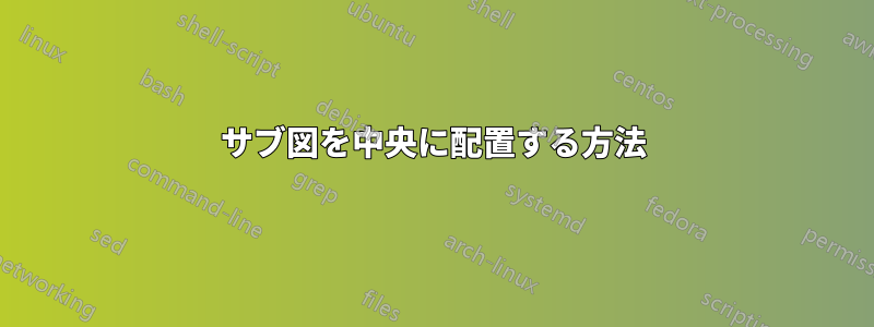
サブ図を使用して 2 つの図を組み合わせましたが、中央に配置されていません。
以下が私のコードです:
\documentclass[10pt]{IEEEtran}
\usepackage{tikz}
\usetikzlibrary{
    shapes.geometric,
    positioning,
    fit,
    calc
}

\usepackage{caption}
\usepackage{subcaption}
\begin{document}
\begin{figure}[t]
\centering
\begin{subfigure}[b]{0.24\textwidth}
\centering
\begin{tikzpicture}[
 block/.style = {circle, draw,
    text width=1em,align=center,inner sep=0pt},
    line/.style = {draw,thick, -latex},
  service/.style={align=left, text width=0.5cm},
node distance=1.0cm and 0.4cm
]

% Place nodes
\node[block](s0){$0$};
\node[service, right of= s0, xshift=10mm, text width=3cm](s10){};
\node[block, below of = s0](s1){$1$};
\node[block, below of =s1](s2){$2$};
\node[block, right of =s2] (s3){$3$};
\node[block, below of =s2] (s4){$4$};
\path [line] (s0)--(s1);
\path [line] (s1)--(s2);
\path [line]  (s1)-|(s3);
\path [line] (s2)--(s4);
\end{tikzpicture}
\caption{1}
\label{fig:workflowsim}
\end{subfigure}
\begin{subfigure}[b]{0.24\textwidth}
\centering
\begin{tikzpicture}[
 block/.style = {circle, draw,
    text width=1em,align=center,inner sep=0pt},
line/.style = {draw,thick, -latex},
  service/.style={align=left, text width=0.5cm},
node distance=1.0cm and 0.4cm
]

% Place nodes
\node[block](s2){$0$} ;
\node[service, right of=s2,xshift=10mm, text width=3cm](s10){};
\node[block, below of =s2] (s4){$4$};
\node[block, below of =s4] (s6){$6$};
\node[block, right of =s6] (s7){$S7$};
\path [line] (s2)--(s4);
\path [line] (s4)--(s6);
\path [line] (s4)-|(s7);
\end{tikzpicture}
\caption{2}
\end{subfigure}
\caption{3}
\end{figure}
\end{document}
そして、以下のような図が表示されます
ご覧のとおり、左の図はa(1)(キャプション)の上にはなく、左揃えになっています。右の図と同様です。
これを解決するにはどうすればよいですか?
答え1
見えなくても、中央揃えに影響するノードがあります。
- ノードが必要ない場合は削除します。
ノードを保持したい場合は、
overlayスペースを占有しないようにオプションを追加します。\node[overlay, service, right of= s0, xshift=10mm, text width=3cm] (s10) {};
このoverlay方法は、矢印の望ましくない移動効果を除去するのにも同様に役立ち、矢印がカバーするスペースはカウントされなくなります。