


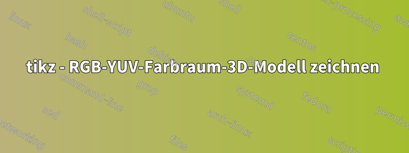
Ich möchte ein 3D-RGB-YUV-Farbraummodell zeichnen, das wie folgt aussieht:

Der RGB-Würfelfarbraum (0,255), die Konvertierungsformel für RGB in YUV lautet:

Formel für YUV zu RGB:

Ich möchte ein genaues Diagramm erhalten, wie es die Formel vorgibt. Welches Paket ist vielleicht besser geeignet, um ein solches Diagramm zu zeichnen?
Antwort1
Ja, man kann Ti lehrenkZ, um lineare Transformationen durchzuführen. Ihr Screenshot zeigt eine nicht-orthographische Projektion. Daher füge ich am Ende der Antwort eine solche Projektion hinzu, obwohl ich sie persönlich nicht so sehr mag. Ich füge eine Funktion hinzu, RGBvecdie die lineare Transformation durchführt (Modulo-Tippfehler, da ich nicht gut darin bin, Texte aus einer Bildschirmanzeige einzutippen, insbesondere wenn ich nicht weiß, woher diese Dinge kommen), und füge einen schnellen Stil hinzu, der RGB-Koordinaten in das andere Farbschema umwandelt. All diese Dinge können angepasst werden, aber zumindest zeigt dies, wie man dies im Prinzip tun kann.
\documentclass[tikz,border=3mm]{standalone}
\usepackage{tikz-3dplot}
\def\matCC{{0.257, 0.504, 0.098},%
        {-0.148, -0.291, 0.439},%
        {0.439, -0.368,0.071}}%
\pgfmathdeclarefunction{RGBvec}{3}{%
\begingroup%
\pgfmathsetmacro{\myY}{16+{\matCC}[0][0]*#1+{\matCC}[0][1]*#2+{\matCC}[0][2]*#3}%
\pgfmathsetmacro{\myCb}{128+{\matCC}[1][0]*#1+{\matCC}[1][1]*#2+{\matCC}[1][2]*#3}%
\pgfmathsetmacro{\myCr}{128+{\matCC}[2][0]*#1+{\matCC}[2][1]*#2+{\matCC}[2][2]*#3}%
\edef\pgfmathresult{\myCr,\myCb,\myY}%
\pgfmathsmuggle\pgfmathresult\endgroup%
}%

\begin{document}
\tdplotsetmaincoords{70}{110}
\begin{tikzpicture}[bullet/.style={circle,inner
    sep=2pt,fill},line cap=round,line join=round,
    RGB coordinate/.code args={(#1,#2,#3)}{\pgfmathparse{RGBvec(#1,#2,#3)}%
    \tikzset{insert path={(\pgfmathresult)}}},font=\sffamily,thick]
 \begin{scope}[tdplot_main_coords,scale=1/40]
  \draw[-stealth] (0,0,0) coordinate (O) -- (280,0,0) coordinate[label=below:Cr] (Cr);
  \draw[-stealth]  (O) -- (0,280,0) coordinate[label=below:Cb] (Cb);
  \draw[-stealth]  (O) -- (0,0,280) coordinate[label=left:Y] (Y);
  \path [RGB coordinate={(255,255,255)}] node[bullet,draw,fill=white] (white){}
    [RGB coordinate={(0,0,0)}] node[bullet] (black){}
    [RGB coordinate={(255,0,0)}] node[bullet,red] (red){}
    [RGB coordinate={(0,255,0)}] node[bullet,green] (green){}
    [RGB coordinate={(0,0,255)}] node[bullet,blue] (blue){}
    [RGB coordinate={(255,0,255)}] node[bullet,magenta] (magenta){}
    [RGB coordinate={(255,255,0)}] node[bullet,yellow] (yellow){}
    [RGB coordinate={(0,255,255)}] node[bullet,cyan] (cyan){};
   \draw (red) -- (black) -- (blue) -- (magenta) -- (red) -- (yellow)
   -- (green) edge (black) -- (cyan) edge (blue) -- (white)  edge (magenta) -- (yellow);
   \draw[thin] (255,0,0) node[left]{255} -- (255,255,0) -- (0,255,0) node[above]{255}
   (0,0,255) node[left]{255} -- (255,0,255) edge (255,0,0)
    -- (255,255,255)  edge (255,255,0) -- (0,255,255)  edge (0,255,0)
   -- cycle ;
 \end{scope}
 \begin{scope}[xshift=8cm,scale=1/40]
  \pgfmathdeclarefunction*{RGBvec}{3}{%
  \begingroup%
  \pgfmathsetmacro{\myY}{16+{\matCC}[0][0]*#1+{\matCC}[0][1]*#2+{\matCC}[0][2]*#3}%
  \pgfmathsetmacro{\myCb}{128+{\matCC}[1][0]*#1+{\matCC}[1][1]*#2+{\matCC}[1][2]*#3}%
  \pgfmathsetmacro{\myCr}{128+{\matCC}[2][0]*#1+{\matCC}[2][1]*#2+{\matCC}[2][2]*#3}%
  \edef\pgfmathresult{\myCb,\myY,\myCr}%
  \pgfmathsmuggle\pgfmathresult\endgroup%
  }%
  \draw[-stealth] (0,0,0) coordinate (O) -- (255,0,0) coordinate[label=below:Cb] (Cb);
  \draw[-stealth]  (O) -- (0,255,0) coordinate[label=left:Y] (Y);
  \draw[-stealth]  (O) -- (0,0,255) coordinate[label=below:Cr] (Cr);
  \path [RGB coordinate={(255,255,255)}] node[bullet,draw,fill=white] (white){}
    [RGB coordinate={(0,0,0)}] node[bullet] (black){}
    [RGB coordinate={(255,0,0)}] node[bullet,red] (red){}
    [RGB coordinate={(0,255,0)}] node[bullet,green] (green){}
    [RGB coordinate={(0,0,255)}] node[bullet,blue] (blue){}
    [RGB coordinate={(255,0,255)}] node[bullet,magenta] (magenta){}
    [RGB coordinate={(255,255,0)}] node[bullet,yellow] (yellow){}
    [RGB coordinate={(0,255,255)}] node[bullet,cyan] (cyan){};
   \draw (red) -- (black) -- (blue) -- (magenta) -- (red) -- (yellow)
   -- (green) edge (black) -- (cyan) edge (blue) -- (white)  edge (magenta) -- (yellow);
  \end{scope}
\end{tikzpicture}
\end{document}

Orthographische Projektionen haben den Vorteil, dass Sie orthogonale Transformationen, also Drehungen, anwenden können und das Ergebnis realistisch ist (bis auf perspektivische Effekte, die mithilfe der Bibliothek behandelt werden können perspective).
\documentclass[tikz,border=3mm]{standalone}
\usepackage{tikz-3dplot}
\def\matCC{{0.257, 0.504, 0.098},%
        {-0.148, -0.291, 0.439},%
        {0.439, -0.368,0.071}}%
\pgfmathdeclarefunction{RGBvec}{3}{%
\begingroup%
\pgfmathsetmacro{\myY}{16+{\matCC}[0][0]*#1+{\matCC}[0][1]*#2+{\matCC}[0][2]*#3}%
\pgfmathsetmacro{\myCb}{128+{\matCC}[1][0]*#1+{\matCC}[1][1]*#2+{\matCC}[1][2]*#3}%
\pgfmathsetmacro{\myCr}{128+{\matCC}[2][0]*#1+{\matCC}[2][1]*#2+{\matCC}[2][2]*#3}%
\edef\pgfmathresult{\myCr,\myCb,\myY}%
\pgfmathsmuggle\pgfmathresult\endgroup%
}%
\tikzset{RGB coordinate/.code args={(#1,#2,#3)}{\pgfmathparse{RGBvec(#1,#2,#3)}%
    \tikzset{insert path={(\pgfmathresult)}}}}
\begin{document}
\foreach \X in {0,10,...,350}
{\tdplotsetmaincoords{70}{\X}
\begin{tikzpicture}[bullet/.style={circle,inner
    sep=2pt,fill},line cap=round,line join=round,font=\sffamily,thick]
 \path[use as bounding box] (-5.5,-2)   rectangle (5.5,8);
 \begin{scope}[tdplot_main_coords,scale=1/40,shift={(-128,-128,0)}]
  \draw[-stealth] (0,0,0) coordinate (O) -- (280,0,0) coordinate[label=below:Cr] (Cr);
  \draw[-stealth]  (O) -- (0,280,0) coordinate[label=below:Cb] (Cb);
  \draw[-stealth]  (O) -- (0,0,280) coordinate[label=left:Y] (Y);
  \path [RGB coordinate={(255,255,255)}] node[bullet,draw,fill=white] (white){}
    [RGB coordinate={(0,0,0)}] node[bullet] (black){}
    [RGB coordinate={(255,0,0)}] node[bullet,red] (red){}
    [RGB coordinate={(0,255,0)}] node[bullet,green] (green){}
    [RGB coordinate={(0,0,255)}] node[bullet,blue] (blue){}
    [RGB coordinate={(255,0,255)}] node[bullet,magenta] (magenta){}
    [RGB coordinate={(255,255,0)}] node[bullet,yellow] (yellow){}
    [RGB coordinate={(0,255,255)}] node[bullet,cyan] (cyan){};
   \draw (red) -- (black) -- (blue) -- (magenta) -- (red) -- (yellow)
   -- (green) edge (black) -- (cyan) edge (blue) -- (white)  edge (magenta) -- (yellow);
   \draw[thin] (255,255,0) -- (255,0,0) node[pos=1.1]{255}
   (255,255,0) --(0,255,0) node[pos=1.1]{255}
   (0,0,255) node[left]{255} -- (255,0,255) edge (255,0,0)
    -- (255,255,255)  edge (255,255,0) -- (0,255,255)  edge (0,255,0)
   -- cycle ;
 \end{scope}
\end{tikzpicture}}
\end{document}

Natürlich kann man die Verbindungen auch mit Farbübergängen gestalten.
\documentclass[tikz,border=3mm]{standalone}
\usepackage{tikz-3dplot}
\def\matCC{{0.257, 0.504, 0.098},%
        {-0.148, -0.291, 0.439},%
        {0.439, -0.368,0.071}}%
\pgfmathdeclarefunction{RGBvec}{3}{%
\begingroup%
\pgfmathsetmacro{\myY}{16+{\matCC}[0][0]*#1+{\matCC}[0][1]*#2+{\matCC}[0][2]*#3}%
\pgfmathsetmacro{\myCb}{128+{\matCC}[1][0]*#1+{\matCC}[1][1]*#2+{\matCC}[1][2]*#3}%
\pgfmathsetmacro{\myCr}{128+{\matCC}[2][0]*#1+{\matCC}[2][1]*#2+{\matCC}[2][2]*#3}%
\edef\pgfmathresult{\myCr,\myCb,\myY}%
\pgfmathsmuggle\pgfmathresult\endgroup%
}%
\tikzset{RGB coordinate/.code args={(#1,#2,#3)}{\pgfmathparse{RGBvec(#1,#2,#3)}%
    \tikzset{insert path={(\pgfmathresult)}}}}
\begin{document}
\tdplotsetmaincoords{70}{110}
\begin{tikzpicture}[bullet/.style={circle,inner
    sep=2pt,outer sep=0pt,fill},connection bar/.style args={(#1)--(#2)}{%
    insert path={let \p1=(#1),\p2=(#2),\n1={atan2(\y2-\y1,\x2-\x1)} in
    [left color=#1,right color=#2,shading angle=\n1+90]
    (#1.\n1-25) arc(\n1-25:\n1+25:40*2pt)
    -- (#2.\n1-180-25)  arc(\n1-180-25:\n1-180+25:40*2pt) -- cycle}},
    line cap=round,line join=round,font=\sffamily,thick]
 \path[use as bounding box] (-5.5,-2)   rectangle (5.5,8);
 \begin{scope}[tdplot_main_coords,scale=1/40,shift={(-128,-128,0)}]
  \draw[-stealth] (0,0,0) coordinate (O) -- (280,0,0) coordinate[label=below:Cr] (Cr);
  \draw[-stealth]  (O) -- (0,280,0) coordinate[label=below:Cb] (Cb);
  \draw[-stealth]  (O) -- (0,0,280) coordinate[label=left:Y] (Y);
  \path [RGB coordinate={(255,255,255)}] node[bullet,draw,fill=white] (white){}
    [RGB coordinate={(0,0,0)}] node[bullet] (black){}
    [RGB coordinate={(255,0,0)}] node[bullet,red] (red){}
    [RGB coordinate={(0,255,0)}] node[bullet,green] (green){}
    [RGB coordinate={(0,0,255)}] node[bullet,blue] (blue){}
    [RGB coordinate={(255,0,255)}] node[bullet,magenta] (magenta){}
    [RGB coordinate={(255,255,0)}] node[bullet,yellow] (yellow){}
    [RGB coordinate={(0,255,255)}] node[bullet,cyan] (cyan){};
  \path[connection bar={(black)--(blue)}];
  \path[connection bar={(blue)--(magenta)}];
  \path[connection bar={(magenta)--(red)}];
  \path[connection bar={(red)--(black)}];
  \path[connection bar={(white)--(magenta)}];
  \path[connection bar={(cyan)--(blue)}];
  \path[connection bar={(green)--(black)}];
  \path[connection bar={(yellow)--(red)}];
  \path[connection bar={(yellow)--(green)}];
  \path[connection bar={(green)--(cyan) }];
  \path[connection bar={(cyan)--(white)}];
  \path[connection bar={(white)--(yellow)}];
   \draw[thin] (255,255,0) -- (255,0,0) node[pos=1.1]{255}
   (255,255,0) --(0,255,0) node[pos=1.1]{255}
   (0,0,255) node[left]{255} -- (255,0,255) edge (255,0,0)
    -- (255,255,255)  edge (255,255,0) -- (0,255,255)  edge (0,255,0)
   -- cycle ;
 \end{scope}
\end{tikzpicture}
\end{document}

Einige Anmerkungen:
- Im Prinzip gibt es einen viel einfacheren Weg, wenn man eine lineare Transformation durchführt:
\begin{scope}[x={(x)},y={(y)},x={(y)}] ... \end{scope}, wobei(x),(y)und(z)die Basisvektoren sind. Aber mit der zusätzlichen Verschiebung wird es etwas verwirrend, und ich dachte, dass es sinnvoll sein könnte, die Koordinaten explizit anzugeben. \pgfshadecolortorgbermöglicht die Konvertierung einer Farbe in RGB-Koordinaten. Als ich diesen Beitrag schrieb, hatte ich nicht daran gedacht, es zu verwenden.
Antwort2
Ein Ausgangspunkt. Jetzt können Sie auf 3D-Koordinaten zeichnen. Wenn ich mir Ihr Profil anschaue, glaube ich, dass Sie das können.
\documentclass[tikz,margin=3]{standalone}
\usetikzlibrary{arrows.meta}
\begin{document}
\begin{tikzpicture}[z={(-135:.5)},>=Stealth]
  \draw[thick,->] (0,0,0) -- (5,0,0) node[below] {Cb};
  \draw[thick,->] (0,0,0) -- (0,5,0) node[left] {Y};
  \draw[thick,->] (0,0,0) -- (0,0,5) node[below] {Cr};
  \draw (4,0,0) node[anchor=135] {255} |- (0,4,0) node[anchor=-30] {255}
    -- (0,4,4) |- (4,0,4) -- cycle
    (0,4,4) -| (4,0,4) (4,4,4) -- (4,4,0)
    (0,0,4) node[anchor=-30] {255};
  \path (0,0) node[below] {0};
\end{tikzpicture}
\end{document}
