


회로도에 사용할 새 요소를 만들고 싶습니다. 지금까지 회로도에 CircuiTikz를 사용했지만 표준 요소를 정의하는 저수준 PGF 명령에는 익숙하지 않습니다. 그림에 그린 것과 같은 간단한 구성 요소를 만드는 가장 쉬운 방법은 무엇입니까? 그래도 나머지 회로 다이어그램에 이를 포함할 수 있어야 합니다.

새 요소를 연결하려는 회로의 코드:
\documentclass[tikz,border=10pt]{standalone}
\usepackage{tikz}
\usepackage{circuitikz}
\begin{document}
\begin{circuitikz}[scale=0.75, american inductors, american voltages, european resistors]
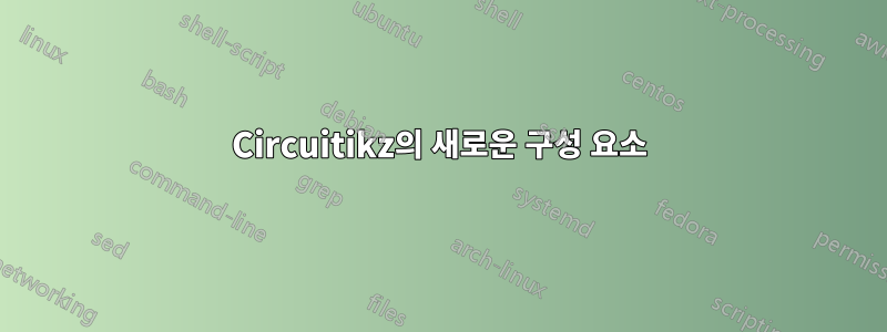
\draw
(0,3.5) to[short] (0.5,4) to[short] (1,4) to[L] (3,4) to[short] (6,4)
(0,3.5) to[short] (0.5,3.5) to[short] (1,3.5) to[L] (3,3.5) to[short] (6,3.5)
(0,3.5) to[short] (0.5,3) to[short] (1,3) to[L] (3,3) to[short] (6,3);
\draw
(0,3.5) to[short, *-] (0,2)
to[R] (0,0)
node[ground] {};
%I want to connect the new component here at the red dot!
\filldraw[fill=red] (0,2.5) circle (0.2);
\end{circuitikz}
\end{document}

빨간 점에 연결하고 싶어요.
답변1
이 같은? 그것은 기반으로합니다John Kormylo의 양극성 튜토리얼:

\documentclass[tikz,border=10pt]{standalone}
\usepackage{tikz}
\usepackage{circuitikz}

\makeatletter
% used to process styles for to-path
\def\TikzBipolePath#1#2{\pgf@circ@bipole@path{#1}{#2}}
% restore size value for bipole definitions
\pgf@circ@Rlen = \pgfkeysvalueof{/tikz/circuitikz/bipoles/length}
\makeatother
\newlength{\ResUp}
\newlength{\ResDown}
\newlength{\ResLeft}
\newlength{\ResRight}

% newcomponent
\ctikzset{bipoles/newcomponent/height/.initial=.50}   % box height
\ctikzset{bipoles/newcomponent/width/.initial=.50}    % box width
\pgfcircdeclarebipole{}                               % no extra anchors
{\ctikzvalof{bipoles/newcomponent/height}}
{newcomponent}                                        % component name
{\ctikzvalof{bipoles/newcomponent/height}}
{\ctikzvalof{bipoles/newcomponent/width}}
{                                                     % component symbol drawing...
  \pgfsetlinewidth{\pgfkeysvalueof{/tikz/circuitikz/bipoles/thickness}\pgfstartlinewidth}
  \pgfextracty{\ResUp}{\northeast}                    % coordinates
  \pgfextracty{\ResDown}{\southwest}
  \pgfextractx{\ResLeft}{\southwest}
  \pgfextractx{\ResRight}{\northeast}
  \pgfpathmoveto{\pgfpoint{\ResDown}{\ResRight}}      % two arc's
  \pgfpatharc{90}{-90}{\ResRight/2}
  \pgfpatharc{90}{-90}{\ResRight/2}
  \pgfpathmoveto{\pgfpoint{\ResUp}{\ResLeft}}         % another two arc's
  \pgfpatharc{90}{-90}{\ResLeft/2}
  \pgfpatharc{90}{-90}{\ResLeft/2}
  \pgfusepath{draw}                                   % draw it!
}
\def\circlepath#1{\TikzBipolePath{newcomponent}{#1}}
\tikzset{newcomponent/.style = {\circuitikzbasekey, /tikz/to path=\circlepath, l=#1}}


\begin{document}
    \begin{circuitikz}[scale=0.75, american inductors, american voltages, european resistors]
        \draw
        (0,3.5) to[short] (0.5,4) to[short] (1,4) to[L] (3,4) to[short] (6,4)
        (0,3.5) to[short] (0.5,3.5) to[short] (1,3.5) to[L] (3,3.5) to[short] (6,3.5)
        (0,3.5) to[short] (0.5,3) to[short] (1,3) to[L] (3,3) to[short] (6,3);

        \draw
        (0,3.5) to[short, *-] (0,2)
        to[newcomponent] (0,0)                       % connect the new component
        to[R] (0,-2)
        node[ground] {};
    \end{circuitikz}
\end{document}