


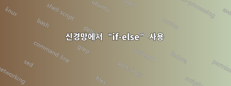
나는 다음과 같이 그리고 싶습니다 :

현재 내가 가지고 있는 것은
내 현재 코드는
\begin{figure}
\centering
\label{fig:nn2}
\begin{tikzpicture}[shorten >=1pt,->,draw=black!50, node distance=\layersep]
    \tikzstyle{every pin edge}=[<-,shorten <=1pt]
    \tikzstyle{neuron}=[circle,fill=black!25,minimum size=17pt,inner sep=0pt]
    \tikzstyle{input neuron}=[neuron, fill=green!50];
    \tikzstyle{output neuron}=[neuron, fill=red!50];
    \tikzstyle{hidden neuron}=[neuron, fill=blue!50];
    \tikzstyle{annot} = [text width=4em, text centered]

    % Draw the input layer nodes
    \foreach \name / \y in {1,...,4}
    % This is the same as writing \foreach \name / \y in {1/1,2/2,3/3,4/4}
        %\if \y in {1,2,3,4}
        \node[input neuron, pin=left:Input \#\y] (I-\name) at (0,-\y) {$x_{\name}$};
        %\else
        %\node[input neuron, pin=left:Input \#\y] (I-\name) at (0,-\y) {$x_{\name}$};
    %\node[input neuron, pin=left:Input \#4] (+1) at (0,-4) {$x_{\name}$};

    % Draw the hidden layer nodes
    \foreach \name / \y in {1,...,4}
        \path[yshift=0.5cm]
            node[hidden neuron] (H-\name) at (\layersep,-\y cm) {$h_{\name}$};

    % Draw the output layer node
    \node[output neuron,pin={[pin edge={->}]right:Output}, right of=H-3] (O) {$y_{0}$};

    % Connect every node in the input layer with every node in the
    % hidden layer.
    \foreach \source in {1,...,4}
        \foreach \dest in {1,...,4}
            \path (I-\source) edge (H-\dest);

    % Connect every node in the hidden layer with the output layer
    \foreach \source in {1,...,4}
        \path (H-\source) edge (O);

    % Annotate the layers
    \node[annot,above of=H-1, node distance=1cm] (hl) {Hidden layer};
    \node[annot,left of=hl] {Input layer};
    \node[annot,right of=hl] {Output layer};
\end{tikzpicture}
\caption{A figure shows the structure of a general neural networks model}
\end{figure}
나는 "if-else"를 사용하려고 노력합니다. 수정 후 내 코드는 다음과 같습니다.
\begin{figure}
\centering
\label{fig:nn2}
\begin{tikzpicture}[shorten >=1pt,->,draw=black!50, node distance=\layersep]
    \tikzstyle{every pin edge}=[<-,shorten <=1pt]
    \tikzstyle{neuron}=[circle,fill=black!25,minimum size=17pt,inner sep=0pt]
    \tikzstyle{input neuron}=[neuron, fill=green!50];
    \tikzstyle{output neuron}=[neuron, fill=red!50];
    \tikzstyle{hidden neuron}=[neuron, fill=blue!50];
    \tikzstyle{annot} = [text width=4em, text centered]

    % Draw the input layer nodes
    \foreach \name / \y in {1,...,4}
    % This is the same as writing \foreach \name / \y in {1/1,2/2,3/3,4/4}
        \if \y in {1,2,3,4}
        \node[input neuron, pin=left:Input \#\y] (I-\name) at (0,-\y) {$x_{\name}$};
        \else
        %\node[input neuron, pin=left:Input \#\y] (I-\name) at (0,-\y) {$x_{\name}$};
    %\node[input neuron, pin=left:Input \#4] (+1) at (0,-4) {$x_{\name}$};

    % Draw the hidden layer nodes
    \foreach \name / \y in {1,...,4}
        \path[yshift=0.5cm]
            node[hidden neuron] (H-\name) at (\layersep,-\y cm) {$h_{\name}$};

    % Draw the output layer node
    \node[output neuron,pin={[pin edge={->}]right:Output}, right of=H-3] (O) {$y_{0}$};

    % Connect every node in the input layer with every node in the
    % hidden layer.
    \foreach \source in {1,...,4}
        \foreach \dest in {1,...,4}
            \path (I-\source) edge (H-\dest);

    % Connect every node in the hidden layer with the output layer
    \foreach \source in {1,...,4}
        \path (H-\source) edge (O);

    % Annotate the layers
    \node[annot,above of=H-1, node distance=1cm] (hl) {Hidden layer};
    \node[annot,left of=hl] {Input layer};
    \node[annot,right of=hl] {Output layer};
\end{tikzpicture}
\caption{A figure shows the structure of a general neural networks model}
\end{figure}
그러나 오류가 있습니다: Extra } 또는 잊어버렸습니다.
감사합니다!
답변1
\fi루프 본문 주위의 중괄호와 if 문을 닫는 중괄호가 누락되었습니다 . 또한 \if명령문은 의도한 대로 작동하지 않습니다.
\if<token1><token2>(문자 코드가 일치하는지 테스트)
\ifTeX는 확장할 수 없는 두 개의 토큰이 발견될 때까지 다음 매크로를 확장합니다 . 두 토큰 중 하나가 제어 시퀀스인 경우 TeX는 해당 제어 시퀀스에 해당하는 현재 항목이\let비활성 문자 토큰과 동일하지 않는 한 문자 코드 256과 범주 코드 16을 갖는 것으로 간주합니다. 이러한 방식으로 각 토큰은 (문자 코드, 범주 코드) 쌍을 지정합니다. 범주 코드와 관계없이 문자 코드가 동일하면 조건이 true입니다. 예를 들어,\def\a{*}and\let\b=*이후 의\def\c{/}테스트에서는\if*\aand\if\a\b가 true가 되지만\if\a\cfalse가 됩니다. 또한\if\a\par거짓이지만\if\par\let사실이 될 것입니다.
(TeXbook 페이지 209)
따라서 첫 번째 반복 단계에서 비교 1하고 i두 번째 2등에서 i는 항상 false로 평가합니다. 대신 다음을 사용하여 마지막 반복 단계인지 확인하고 있습니다 \ifnum.
\begin{figure}
\centering
\label{fig:nn2}
\begin{tikzpicture}[shorten >=1pt,->,draw=black!50, node distance=\layersep]
    \tikzstyle{every pin edge}=[<-,shorten <=1pt]
    \tikzstyle{neuron}=[circle,fill=black!25,minimum size=17pt,inner sep=0pt]
    \tikzstyle{input neuron}=[neuron, fill=green!50];
    \tikzstyle{output neuron}=[neuron, fill=red!50];
    \tikzstyle{hidden neuron}=[neuron, fill=blue!50];
    \tikzstyle{annot} = [text width=4em, text centered]
    \newcommand{\n}{4} % number of neurons per layer

    % Draw the input layer nodes
    \foreach \name / \y in {1,...,\n}{
    % This is the same as writing \foreach \name / \y in {1/1,2/2,3/3,4/4}
        \ifnum \y=\n
            \node[input neuron, pin=left:Input \#$n$] (I-\name) at (0,-\y) {$x_{n}$};
        \else
            \node[input neuron, pin=left:Input \#\y] (I-\name) at (0,-\y) {$x_{\name}$};
        \fi
    }

    % Draw the hidden layer nodes
    \foreach \name / \y in {1,...,\n}{
        \ifnum \y=\n
            \path[yshift=0.5cm] node[hidden neuron] (H-\name) at (\layersep,-\y cm) {$h_{n}$};
        \else
            \path[yshift=0.5cm] node[hidden neuron] (H-\name) at (\layersep,-\y cm) {$h_{\name}$};
        \fi
    }

    % Draw the output layer node
    \node[output neuron,pin={[pin edge={->}]right:Output}, right of=H-3] (O) {$y_{0}$};

    % Connect every node in the input layer with every node in the
    % hidden layer.
    \foreach \source in {1,...,\n}
        \foreach \dest in {1,...,\n}
            \path (I-\source) edge (H-\dest);

    % Connect every node in the hidden layer with the output layer
    \foreach \source in {1,...,\n}
        \path (H-\source) edge (O);

    % Annotate the layers
    \node[annot,above of=H-1, node distance=1cm] (hl) {Hidden layer};
    \node[annot,left of=hl] {Input layer};
    \node[annot,right of=hl] {Output layer};
\end{tikzpicture}
\caption{A figure shows the structure of a general neural networks model}
\end{figure}
그러나 다음과 같은 경우에는 아무것도 사용하지 않을 것입니다.
\begin{figure}
\centering
\label{fig:nn2}
\begin{tikzpicture}[shorten >=1pt,->,draw=black!50, node distance=\layersep]
    \tikzstyle{every pin edge}=[<-,shorten <=1pt]
    \tikzstyle{neuron}=[circle,fill=black!25,minimum size=17pt,inner sep=0pt]
    \tikzstyle{input neuron}=[neuron, fill=green!50];
    \tikzstyle{output neuron}=[neuron, fill=red!50];
    \tikzstyle{hidden neuron}=[neuron, fill=blue!50];
    \tikzstyle{annot} = [text width=4em, text centered]
    \newcommand{\numberNeuronsPerLayer}{4}
    \edef\numberNeuronsPerLayerMinusOne{\number\numexpr\numberNeuronsPerLayer-1\relax}

    % Draw the input layer nodes
    \foreach \name / \y in {1,...,\numberNeuronsPerLayerMinusOne}{
    % This is the same as writing \foreach \name / \y in {1/1,2/2,3/3,4/4}
        \node[input neuron, pin=left:Input \#\y] (I-\name) at (0,-\y) {$x_{\name}$};
    }
    \node[input neuron, pin=left:Input \#$n$] (I-\numberNeuronsPerLayer) at (0,-\numberNeuronsPerLayer) {$x_{n}$};

    % Draw the hidden layer nodes
    \begin{scope}[yshift=0.5cm]
        \foreach \name / \y in {1,...,\numberNeuronsPerLayerMinusOne}{
            \path node[hidden neuron] (H-\name) at (\layersep,-\y cm) {$h_{\name}$};
        }
        \path node[hidden neuron] (H-\numberNeuronsPerLayer) at (\layersep,-\numberNeuronsPerLayer cm) {$h_{n}$};
    \end{scope}

    % Draw the output layer node
    \node[output neuron,pin={[pin edge={->}]right:Output}, right of=H-3] (O) {$y_{0}$};

    % Connect every node in the input layer with every node in the
    % hidden layer.
    \foreach \source in {1,...,\numberNeuronsPerLayer}
        \foreach \dest in {1,...,\numberNeuronsPerLayer}
            \path (I-\source) edge (H-\dest);

    % Connect every node in the hidden layer with the output layer
    \foreach \source in {1,...,\numberNeuronsPerLayer}
        \path (H-\source) edge (O);

    % Annotate the layers
    \node[annot,above of=H-1, node distance=1cm] (hl) {Hidden layer};
    \node[annot,left of=hl] {Input layer};
    \node[annot,right of=hl] {Output layer};
\end{tikzpicture}
\caption{A figure shows the structure of a general neural networks model}
\end{figure}
답변2
귀하의 답변에 기초하여 질문:

\documentclass[tikz, margin=3mm]{standalone}
\usetikzlibrary{calc, chains, positioning}

\begin{document}
    \begin{tikzpicture}[shorten >=1pt,->, draw=black!50,
        node distance = 6mm and 24mm,
          start chain = going below,
every pin edge/.style = {<-,shorten <=1pt},
        neuron/.style = {circle, fill=#1,
                         minimum size=17pt, inner sep=0pt},
         annot/.style = {text width=4em, align=center}
                        ]
% Draw the input and hidden layer nodes
\ifnum\i<4
    \node[neuron=green!50, on chain,
          pin=180:Input \#\i    % if you not like to have this inputs, just erase them
          ]              (I-\i)  {$x_{\i}$};
    \node[neuron=blue!50,
      right=of I-\i]     (H-\i)  {};
\else
    \node[neuron=green!50, on chain,
          pin=180:Input \#\i    % if you not like to have this inputs, just erase them
          ]              (I-\i)  {$+1$};
    \node[neuron=blue!50,
          right=of I-\i] (H-\i)  {$+1$};
\fi
}
% Draw the output layer node
    \node[neuron=red!50,
          right=of $(H-2)!0.5!(H-3)$]  (O-1)   {};
% Connect input nodes with hidden nodes and
%  hiden nodes with output nodes with the output layer
    \foreach \i in {1,...,4}
        \foreach \j in {1,...,4}
{
    \draw (I-\i) edge (H-\j)
          (H-\j) edge (O-1);
}
    \draw (O-1) -- node[below] {$h_{w,b}(x)$} + (2,0);
% Annotate layers
\node[annot,below=of I-4.center]        {Layer 1};
\node[annot,below=of H-4.center]        {Layer 2};
\node[annot,below=of O-1 |- H-4.center] {Layer 3};
    \end{tikzpicture}
\end{document}
조건부: 위의 MWE에서 다음과 같습니다.
\ifnum\i<4
    action 1
\else
    action 2
\fi;
부록: 조건문 없이 해결할 수 있는 문제:
\documentclass[tikz, margin=3mm]{standalone}
\usetikzlibrary{calc, chains, positioning}

\begin{document}
    \begin{tikzpicture}[shorten >=1pt,->, draw=black!50,
        node distance = 6mm and 24mm,
          start chain = going below,
every pin edge/.style = {<-,shorten <=1pt},
        neuron/.style = {circle, fill=#1,
                         minimum size=17pt, inner sep=0pt},
         annot/.style = {text width=4em, align=center}
                        ]
% Draw the input and hyden layer nodes
\foreach \i in {1,2,3}
{
    \node[neuron=green!50, on chain,
          pin=180:Input \#\i    % if you not like to have this inputs, just erase them
          ]             (I-\i)  {$x_{\i}$};
    \node[neuron=blue!50,
      right=of I-\i]    (H-\i)     {};
}
    \node[neuron=green!50,
          pin=180:Input \#\i    % if you not like to have this inputs, just erase them
          below=of I-3
          ]              (I-4)  {$+1$};
    \node[neuron=blue!50,
          below=of H-3] (H-4)  {$+1$};
% Draw the output layer node
    \node[neuron=red!50,
          right=of $(H-2)!0.5!(H-3)$]  (O-1)   {};
% Connect input nodes with hidden nodes and
%  hiden nodes with output nodes with the output layer
    \foreach \i in {1,...,4}
        \foreach \j in {1,...,4}
{
    \draw (I-\i) edge (H-\j)
          (H-\j) edge (O-1);
}
    \draw (O-1) -- node[below] {$h_{w,b}(x)$} + (2,0);
% Annotate layers
\node[annot,below=of I-4.center]        {Layer 1};
\node[annot,below=of H-4.center]        {Layer 2};
\node[annot,below=of O-1 |- H-4.center] {Layer 3};
    \end{tikzpicture}
\end{document}
결과는 이전과 같습니다.