


我試圖在放置在子圖環境中的兩個不同的 tikz 繪圖之間繪製線條,例如左圖像中的小藍色矩形的角落和右圖像的軸環境的角落。

由於這兩個數字會變得非常大,我需要用 匯出它們externalize。因此我也想使用該subfig庫而不是groupplots.
remember picture我認為它可以與和關鍵字一起使用overlay,但第一次嘗試只會帶來錯誤,所以我擔心可能會與remember picture和發生衝突externalize。我已經找到了一個很好的描述如何引用矩形的角。
是否可以按照範例圖片所示繪製線條?是否可以結合使用externalizeand subfig(如果不是,我更喜歡groupplotsand externalizebeforesubfig和 no externalize,儘管覆蓋圖像不需要“外部化”)?
這是我的最小範例:
\documentclass[parskip]{scrartcl}
\usepackage{tikz,pgfplots,subfig, lipsum}
% \usetikzlibrary{external}
% \tikzexternalize[figure list=true]
\begin{document}

\lipsum[1]
\begin{figure}[h]
    \centering
    \subfloat[Overview.]{
        \begin{tikzpicture}[trim axis left, trim axis right]
            \begin{axis}[domain=-10:10,x post scale=0.5]
                \addplot+[red,mark=none]{x^2};
                \draw[fill=blue,opacity=0.3] (axis cs:-2,-0.5) rectangle (axis cs:2,5);
            \end{axis}
        \end{tikzpicture}
    }\quad
    \subfloat[Detail.]{
        \begin{tikzpicture}[trim axis left, trim axis right]
            \begin{axis}[xmin=-2,xmax=2,ymin=-0.5,ymax=5,domain=-2:2,mark=none]
                \addplot+[red,mark=none]{x^2};
            \end{axis}
        \end{tikzpicture}
    }
    \caption{Curve.}
\end{figure}
\lipsum[2]

\end{document}
多謝!
答案1
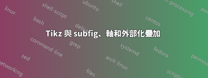
為了完整起見,我提供了該groupplots方法的簡短版本,其中包含偽造的副標題和可能的外化。有不同的方法(請參閱問題下的評論),但這對我來說似乎是最簡單的。然而,對於原圖我意識到額外的線條只會讓一切變得混亂...

這裡是程式碼:
\documentclass[parskip]{scrartcl}
\usepackage{tikz,pgfplots,subfig, lipsum}
\usetikzlibrary{pgfplots.groupplots}
\usetikzlibrary{fit,intersections,}
\makeatletter
\tikzset{ % fitting node, see http://goo.gl/KOvpQ
  fitting node/.style={
    inner sep=0pt,
    fill=none,
    draw=none,
    reset transform,
    fit={(\pgf@pathminx,\pgf@pathminy) (\pgf@pathmaxx,\pgf@pathmaxy)}
  },
  reset transform/.code={\pgftransformreset}
}
\makeatother
% \usetikzlibrary{external}
% \tikzexternalize[figure list=true]
\begin{document}

\lipsum[1]
\begin{figure}[h]
    \centering
        \begin{tikzpicture}
            \begin{groupplot}[domain=-10:10,group style={group size=2 by 1,vertical sep=0.7cm,horizontal sep=1.05cm,xlabels at=edge bottom,ylabels at=edge left},x label style={font=\footnotesize}]
                \nextgroupplot[x post scale=0.5,xlabel={(a) Overview.},]
                    \addplot+[red,mark=none]{x^2};
                    \draw[fill=blue,opacity=0.3] (axis cs:-2,-0.5) rectangle (axis cs:2,5) node[fitting node] (rect) {};
                \nextgroupplot[xmin=-2,xmax=2,ymin=-0.5,ymax=5,domain=-2:2,mark=none,x post scale=0.9, xlabel={(b) Detail.}]
                    \addplot+[red,mark=none]{x^2};
            \end{groupplot}

            \draw[dashed] (rect.north west) -- (group c2r1.north west);
            \draw[dashed] (rect.south west) -- (group c2r1.south west);
            \path[name path=lineA] (rect.south east) -- (group c2r1.south east);
            \path[name path=lineB] (rect.north east) -- (group c2r1.north east);
            \path[name path=lineC] (group c2r1.north west) -- (group c2r1.south west);

            \draw [dashed,name intersections={of=lineA and lineC, by=pA}] (rect.south east) -- (pA);
            \draw [dashed,name intersections={of=lineB and lineC, by=pB}] (rect.north east) -- (pB);
            \draw [dashed,gray!90,opacity=0.7] (pA) -- (group c2r1.south east);
            \draw [dashed,gray!90,opacity=0.7] (pB) -- (group c2r1.north east);

        \end{tikzpicture}
\end{figure}

\lipsum[2]
\end{document}