


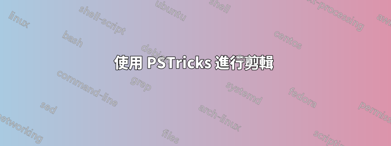
考慮以下範例。
程式碼
\documentclass{article}

\usepackage{pstricks-add}

\begin{document}

\begin{figure}
\psset{unit=0.05}
 \begin{pspicture}(120,216)
  \pnodes{P}(0,0)(0,120)(186,120)(216,120)(216,0)(186,0)(186,30)(186,90)
  \pspolygon(P0)(P1)(P3)(P4)
  \pcline[offset=12pt]{|<->|}(P1)(P3)
  \ncput*[nrot=:U]{216}
  \pcline[offset=12pt]{|<->|}(P3)(P4)
  \ncput*[nrot=:U]{120}
  \pspolygon[linestyle=none,fillstyle=vlines](P2)(P3)(P4)(P5)
  \pswedge[linestyle=none,fillstyle=solid,fillcolor=white](P6){30}{270}{90}
  \pswedge[linestyle=none,fillstyle=solid,fillcolor=white](P7){30}{270}{90}
  \psarc(P6){30}{270}{90}
  \psarc(P7){30}{270}{90}
  \psdot(P6)
  \psdot(P7)
 \end{pspicture}
\end{figure}

\end{document}
輸出

問題
上面的程式碼似乎是創建圖形的錯誤方法。我想這\pscustom是可行的方法,但我不知道如何使用它;如何使用 PSTricks 以「最佳」方式產生圖形? (我非常想看看它是如何完成的,而不僅僅是得到關於使用這個或那個的評論。)
答案1
兩個框架和兩個圓弧 或\pscustom:
\documentclass{article}
\usepackage{pstricks-add}
\begin{document}

\psset{unit=1pt}
\begin{pspicture}(240,140)
\psframe[dimen=middle](216,120)
\psframe[fillstyle=vlines,linestyle=none](186,0)(216,120)
\psarc[fillstyle=solid,fillcolor=white](186,30){30}{-90}{90}
\psarc[fillstyle=solid,fillcolor=white](186,90){30}{-90}{90}
\psdots(186,30)(186,90)
\pcline[offset=12pt]{|<->|}(0,120)(216,120) \ncput*{216}
\pcline[offset=12pt]{|<->|}(216,120)(216,0) \ncput*[nrot=:U]{120}
\end{pspicture}

\begin{pspicture}(240,140)
\psframe[dimen=middle](216,120)
\pscustom[fillstyle=vlines,hatchcolor=red]{%
  \psarc(186,30){30}{-90}{90}
  \psarc(186,90){30}{-90}{90}
  \psline(186,120)(216,120)(216,0)
}
\psdots(186,30)(186,90)
\pcline[offset=12pt]{|<->|}(0,120)(216,120) \ncput*{216}
\pcline[offset=12pt]{|<->|}(216,120)(216,0) \ncput*[nrot=:U]{120}
\end{pspicture}

\end{document}

由於\psframe繪製了一條閉合路徑(正確剪切所需),因此\pscustom如果使用剪切函數,也可以將其添加為最後一個組件:
\documentclass{article}
\usepackage{pstricks-add}% http://tug.org/PSTricks/main.cgi/
\begin{document}

\begin{figure}
\psset{unit=1pt}
\begin{pspicture}(240,140)
\psclip{\psset{linestyle=solid}
  \pscustom{
    \psarc(186,30){30}{-90}{90}
    \psarc(186,90){30}{-90}{90}
    \psframe[dimen=middle](216,120)
  }
}
  \psframe[fillstyle=vlines,linestyle=none](186,0)(216,120)
\endpsclip
\psdots(186,30)(186,90)
\pcline[offset=12pt]{|<->|}(0,120)(216,120) \ncput*{216}% Top dimension
\pcline[offset=12pt]{|<->|}(216,120)(216,0) \ncput*[nrot=:U]{120}% Right dimension
\end{pspicture}
\end{figure}

\end{document}
這也有效,因為結構和\psframe繪製方式(從中左逆時針方向)。
答案2
我正在努力改進現有的答案。
- 箭頭說明符
|<->|應變更為|<*->|*以使|類似提示正確對齊。 - 最好全域傳遞
dimen=middle而\pscustom不是本地指定給預設情況下的每個命令dimen=outer。 由於剪切區域是在描畫剪切器路徑之後繪製的,因此通常需要在剪切後再次描繪剪切器路徑。
如果你想明白我的意思,我已經添加到維爾納編輯的
hatchcolor=red,hatchsep=1pt剪輯中。\psframe原本Werner的設定是hatchcolor=black不易察覺的,但現在隨著顏色的變化,「缺陷」在視覺上就很明顯了,如下圖所示。
這就是為什麼修剪後需要重新撫摸的原因。
unit=1pt應避免使用,因為導航網格會變得混亂。

\documentclass[pstricks,border=12pt]{standalone}
\usepackage{pst-node}
\def\Path[#1]{%
  \pscustom[dimen=middle,#1]{
    \psarc(186,30){30}{-90}{90}
    \psarc(186,90){30}{-90}{90}
    \psframe(216,120)
  }\ignorespaces
}

\begin{document}

\psset{unit=1pt,linewidth=3pt}
\begin{pspicture}(240,140)
\psclip{\Path[linestyle=none]}
  \psframe[fillstyle=vlines,hatchcolor=red,hatchsep=1pt,linestyle=none](186,0)(216,120)
\endpsclip
\Path[]
\psdots(186,30)(186,90)
\pcline[offset=12pt]{|<*->|*}(0,120)(216,120) \ncput*{216}% Top dimension
\pcline[offset=12pt]{|<*->|*}(216,120)(216,0) \ncput*[nrot=:U]{120}% Right dimension
\end{pspicture}

\end{document}