


Tikz 擁有一堆有用的數位電路組件,無論是基本的還是複雜的。在這裡,我需要一些我自己的,甚至不一定是方便的之一。但讓我們舉一個相當方便的例子:幅度比較器。
我想要這個幅度比較器我的任務的組件,其信號端口定義為anchors。我可以製作一個盒子,在連接埠上貼上標籤並在上面寫上名稱,但那是不夠!
我還需要展示裡面的內容。細節不應超出柵極,我不想要晶體管,但我確實需要閘極。
這是我到目前為止所掌握的內容,其中大部分只是複製/模仿的這個(著名的?)資料觸發器範例:
\makeatletter

% Magnitude Comparator (magn comparator) shape
\pgfdeclareshape{magn comparator}
{
    % The 'minimum width' and 'minimum height' keys, not the content, determine
    % the size
    \savedanchor\northeast
    {%
        \pgfmathsetlength\pgf@x{\pgfshapeminwidth}%
        \pgfmathsetlength\pgf@y{\pgfshapeminheight}%
        \pgf@x=0.5\pgf@x
        \pgf@y=0.5\pgf@y
    }
    % This is redundant, but makes some things easier:
    \savedanchor\southwest
    {%
        \pgfmathsetlength\pgf@x{\pgfshapeminwidth}%
        \pgfmathsetlength\pgf@y{\pgfshapeminheight}%
        \pgf@x=-0.5\pgf@x
        \pgf@y=-0.5\pgf@y
    }
    % Inherit from rectangle
    \inheritanchorborder[from=rectangle]

    % Define same anchor a normal rectangle has
    \anchor{center}{\pgfpointorigin}
    \anchor{north}{\northeast \pgf@x=0pt}
    \anchor{east}{\northeast \pgf@y=0pt}
    \anchor{south}{\southwest \pgf@x=0pt}
    \anchor{west}{\southwest \pgf@y=0pt}
    \anchor{north east}{\northeast}
    \anchor{north west}{\northeast \pgf@x=-\pgf@x}
    \anchor{south west}{\southwest}
    \anchor{south east}{\southwest \pgf@x=-\pgf@x}
    \anchor{text}
    {
        \pgfpointorigin
        \advance\pgf@x by -.5\wd\pgfnodeparttextbox%
        \advance\pgf@y by -.5\ht\pgfnodeparttextbox%
        \advance\pgf@y by +.5\dp\pgfnodeparttextbox%
    }

    % Define anchors for input signal ports
    \anchor{input gt}
    {
        \pgf@process{\southwest}%
        \pgf@y=-.5\pgf@y%
    }
    \anchor{input eq}
    {
        \pgf@process{\southwest}%
        \pgf@y=0pt%
    }
    \anchor{input lt}
    {
        \pgf@process{\southwest}%
        \pgf@y=.5\pgf@y%
    }
    \anchor{input a}
    {
        \pgf@process{\northeast}%
        \pgf@x=-.3\pgf@x%
    }
    \anchor{input b}
    {
        \pgf@process{\northeast}%
        \pgf@x=.3\pgf@x%
    }

    % Define anchors for output signal ports
    \anchor{output gt}
    {
        \pgf@process{\northeast}%
        \pgf@y=.5\pgf@y%
    }
    \anchor{output eq}
    {
        \pgf@process{\northeast}%
        \pgf@y=0pt%
    }
    \anchor{output lt}
    {
        \pgf@process{\northeast}%
        \pgf@y=-.5\pgf@y%
    }

    % Draw the rectangle box and the port labels
    \backgroundpath
    {
        % Rectangle box
        \pgfpathrectanglecorners{\southwest}{\northeast}
        % \node [and gate] (kek) at (0, 0) {};
    }
}

% Define default style for this node
\tikzset
{
    every magn comparator node/.style =
    {
        draw,
        minimum width = 2cm,
        minimum height = 2cm,
        thick,
        inner sep = 1mm,
        outer sep = 0pt,
        cap = round
    }
}

\makeatother
這是一個單獨的文件,我將其包含在主 LaTeX 文件的序言中。
這裡沒有門,只是拉出一個盒子。我試圖按照我在這件事之外所做的通常方式簡單地放置一個隨機與門\pgfdeclareshape,這當然不起作用。我評論了那個嘗試。
我應該有一種方法可以在現有形狀的基礎上定義更多形狀。它是什麼?
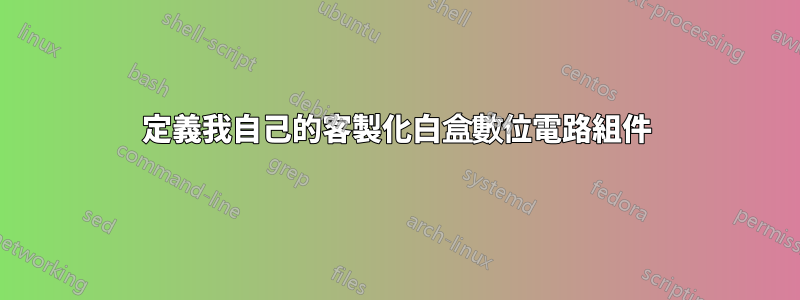
編輯:我期望我手中有這樣的東西,我應該能夠放置它並且可以輕鬆地到達它的端口作為錨點,類似於 AND/OR/NOR/XOR/NAND 閘:

請注意,盒子的內部並沒有真正起到幅度比較器的作用,它只是我所期望的虛擬範例。
答案1
取決於您的用例的複雜性以及您需要多少個這些形狀……這是一個開始。
答案如下:
rectangle ee借用了定義的形狀聲明circuits.ee(這只是藉用了帶有和錨點的rectangle形狀)。.input.output我也從連結借用範例用於形狀定義內的文字。錨點設定為
\pgfpointlineattime(這類似於pos沿直線的關鍵點,或 符號中的因子calc)($(<p1>)!<factor>!(<p2>)$)。如果您有更多這樣的形狀,需要沿著矩形邊框使用多個不同的錨點,則可以使用 fey 鍵和形狀聲明內的循環來序列化。這也適用於文字。
現在我們有了一個帶有錨點和文字的形狀,我們可以使用它了。為了獲得正確的電路形狀,我們使用 聲明一個符號
circuit declare symbol並使用 進行設定set <symbol name> graphic。鍵
circuit symbol size設定minimum width和與(引擎蓋下的 TeX 尺寸)minimum height相關。circuit symbol unit這使得它相對於其他電路符號具有可擴展性。需要鑰匙transform shape才能使其沿著circuits路徑旋轉to。path picture使用建議的程式碼我的另一個答案。設定隨節點旋轉和縮放的局部座標系: 座標(0, 0)位於節點的中心。這X向量指向east(=output),y向量到北錨。這對於座標規範很重要,(left:.2)因為它使用.2節點水平尺寸的一半和所應用的旋轉。內部的電路符號
path picture獲得選項gray(與線條一樣),並且circuit symbol unit=.1cm確實將符號縮小到適當的大小。可能需要調整該值以獲得正確的大小。也可以使其依賴前述具有尺寸\pgf@xx和 的局部座標系\pgf@yy。顯然,如果您需要具有相同錨點和連接佈局但具有不同閘的多個符號,則可以根據三個值鍵使形狀定義可延展,在本例中這三個值鍵設為
not gate、nand gate和nor gate。
我已經用我的paths.ortho圖書館對於 內部的連接path picture。顯然您可以使用任何方式連接這些線。
程式碼
\documentclass[tikz]{standalone}
\usetikzlibrary{circuits.ee,circuits.logic.US,paths.ortho}
\makeatletter
\pgfdeclareshape{my complicated box}{%
  \inheritsavedanchors[from=rectangle ee]
  \inheritanchor[from=rectangle ee]{center}
  \inheritanchor[from=rectangle ee]{north}
  \inheritanchor[from=rectangle ee]{south}
  \inheritanchor[from=rectangle ee]{east}
  \inheritanchor[from=rectangle ee]{west}
  \inheritanchor[from=rectangle ee]{north east}
  \inheritanchor[from=rectangle ee]{north west}
  \inheritanchor[from=rectangle ee]{south east}
  \inheritanchor[from=rectangle ee]{south west}
  \inheritanchor[from=rectangle ee]{input}
  \inheritanchor[from=rectangle ee]{output}
  \inheritanchorborder[from=rectangle ee]
  \inheritbackgroundpath[from=rectangle ee]
  \anchor{eq in} {\pgf@sh@reanchor{\pgf@sm@shape@name}{input}}
  \anchor{eq out}{\pgf@sh@reanchor{\pgf@sm@shape@name}{output}}
  \anchor{lt in}{%
    \pgfpointlineattime{.2}{\southwest}
    {\southwest\pgf@xc\pgf@x\northeast\pgf@x\pgf@xc}}
  \anchor{gt in}{%
    \pgfpointlineattime{.8}{\southwest}
    {\southwest\pgf@xc\pgf@x\northeast\pgf@x\pgf@xc}}
  \anchor{gt out}{%
    \pgfpointlineattime{.3}{\northeast}
    {\southwest\pgf@yc\pgf@y\northeast\pgf@y\pgf@yc}}
  \anchor{lt out}{%
    \pgfpointlineattime{.7}{\northeast}
    {\southwest\pgf@yc\pgf@y\northeast\pgf@y\pgf@yc}}
  \anchor{a}{%
    \pgfpointlineattime{.4}
      {\southwest\pgf@xc\pgf@x\northeast\pgf@x\pgf@xc}{\northeast}}
  \anchor{b}{%
    \pgfpointlineattime{.6}
      {\southwest\pgf@xc\pgf@x\northeast\pgf@x\pgf@xc}{\northeast}}
  \beforebackgroundpath{%
    \begingroup
      \tikzset{my complicated box/labels/.try}\tikz@textfont
      \pgf@sh@reanchor{\pgf@sm@shape@name}{eq in}
      \pgftext[at=\pgfqpoint{\pgf@x}{\pgf@y},left,%
                x=\pgfkeysvalueof{/pgf/inner xsep}]{$\mathrm{eq}_{\mathrm{in}}$}
      \pgf@sh@reanchor{\pgf@sm@shape@name}{eq out}
      \pgftext[at=\pgfqpoint{\pgf@x}{\pgf@y},right,%
                x=-\pgfkeysvalueof{/pgf/inner xsep}]{$\mathrm{eq}_{\mathrm{out}}$}
      \pgf@sh@reanchor{\pgf@sm@shape@name}{gt in}
      \pgftext[at=\pgfqpoint{\pgf@x}{\pgf@y},left,%
                x=\pgfkeysvalueof{/pgf/inner xsep}]{$\mathrm{gt}_{\mathrm{in}}$}
      \pgf@sh@reanchor{\pgf@sm@shape@name}{gt out}
      \pgftext[at=\pgfqpoint{\pgf@x}{\pgf@y},right,%
                x=-\pgfkeysvalueof{/pgf/inner xsep}]{$\mathrm{gt}_{\mathrm{out}}$}
      \pgf@sh@reanchor{\pgf@sm@shape@name}{lt in}
      \pgftext[at=\pgfqpoint{\pgf@x}{\pgf@y},left,%
                x=\pgfkeysvalueof{/pgf/inner xsep}]{$\mathrm{lt}_{\mathrm{in}}$}
      \pgf@sh@reanchor{\pgf@sm@shape@name}{lt out}
      \pgftext[at=\pgfqpoint{\pgf@x}{\pgf@y},right,%
                x=-\pgfkeysvalueof{/pgf/inner xsep}]{$\mathrm{lt}_{\mathrm{out}}$}
      \pgf@sh@reanchor{\pgf@sm@shape@name}{a}
      \pgftext[at=\pgfqpoint{\pgf@x}{\pgf@y},top,%
                y=-\pgfkeysvalueof{/pgf/inner ysep}]{a\vphantom{b}}
      \pgf@sh@reanchor{\pgf@sm@shape@name}{b}
      \pgftext[at=\pgfqpoint{\pgf@x}{\pgf@y},top,%
                y=-\pgfkeysvalueof{/pgf/inner ysep}]{b}
    \endgroup}
}
\makeatother
\tikzset{my complicated box/labels/.style={font=\footnotesize, inner sep=.1667em}}
\tikzset{
  circuit declare symbol=my complicated symbol,
  set my complicated symbol graphic={
    draw, shape=my complicated box, circuit symbol size=width 10 height 8,
    transform shape,
    path picture={
      \expandafter\let\expandafter\tfn\csname tikz@fig@name\endcsname
      \pgftransformshift{\pgfpointanchor{\tfn}{center}}%
      \pgfsetxvec{\pgfpointdiff{\pgfpointanchor{\tfn}{center}}
                 {\pgfpointanchor{\tfn}{east}}}%
      \pgfsetyvec{\pgfpointdiff{\pgfpointanchor{\tfn}{center}}
                 {\pgfpointanchor{\tfn}{north}}}
      \tikzset{every circuit symbol/.append style={circuit symbol unit=.1cm, gray}}
      \path[thin, draw=gray]
        (\tfn.eq in) to[not gate=near end] (\tfn.eq out)
        (\tfn.lt out) to ++ (left:.2)
          node[anchor=output, logic gate inputs=nn, nand gate] (\tfn-nand) {}
        (\tfn-nand.input 2) to[-|-=.6] (\tfn.lt in)
        (\tfn-nand.input 1) to[-|] (\tfn.a)
        (\tfn.gt out) to ++ (left:.2)
          node[anchor=output, logic gate inputs=nn, nor gate] (\tfn-nor) {}
        (\tfn-nor.input 2) to[-|-=.6] (\tfn.gt in)
        (\tfn-nor.input 1) to[-|] (\tfn.b);
    }},
}
\begin{document}
\begin{tikzpicture}[circuit logic US]
\draw (0,0) to[my complicated symbol] ++ (30:4);
\end{tikzpicture}
\end{document}
輸出

答案2
一個可能的解決方案是pics.很難用於pic-anchors定位(錨定 TiKZ 圖片)但它們可以作為繪製它們之間的連結的參考點。
\documentclass[tikz,border=2mm]{standalone}

\usetikzlibrary{positioning,circuits.logic.US, fit}

\tikzset{
    mycircuit/.pic={
        \begin{scope}[circuit logic US]
        \node[gray, thick, draw, nor gate] (-gt) at (2,0.75) {};
        \node[gray, thick, draw, not gate] (-eq) at (2,0) {};
        \node[gray, thick, draw, nand gate] (-lt) at (2,-0.75) {};

        \draw[gray] (-gt.output)--++(3mm,0)
             coordinate[label={[black]left:$\mathrm{gt}_\mathrm{out}$}] (-gtout);

        \draw[gray] (-eq.output)--(-eq.output-|-gtout)
             coordinate[label={[black]left:$\mathrm{eq}_\mathrm{out}$}] (-eqout);

        \draw[gray] (-lt.output)--(-lt.output-|-gtout)
             coordinate[label={[black]left:$\mathrm{lt}_\mathrm{out}$}] (-eqout);

        \draw[gray] (-gt.input 1)-|++(-3mm,.5cm)
             coordinate[label={[black]below:$\mathrm{b}$}] (-b);

        \draw[gray] (-lt.input 1)-|([xshift=-6mm]-b.center)
             coordinate[label={[black]below:$\mathrm{a}$}] (-a);

        \draw[gray] (-eq.input)--++(-2cm,0)
             coordinate[label={[black]right:$\mathrm{eq}_\mathrm{in}$}] (-eqin);

        \draw[gray] (-gt.input 2)--++(-1.2cm,0) |- ([yshift=1cm]-eqin.center)
             coordinate[label={[black]right:$\mathrm{gt}_\mathrm{in}$}] (-gtin);

        \draw[gray] (-lt.input 2)--++(-1.2cm,0) |- ([yshift=-1cm]-eqin.center)
             coordinate[label={[black]right:$\mathrm{lt}_\mathrm{in}$}] (-ltin);

        \node[draw, fit={(-ltin) (-b) ([yshift=-.5cm]-lt.input 2) (-gtout)},
              inner sep=0pt] (-box) {};
        \end{scope}
    }}

\begin{document}
\begin{tikzpicture}

\pic (a) at (0,0) {mycircuit};

\pic (b) at (5,1) {mycircuit};

\draw (a-gtout) -- (b-gtin);
\draw ([yshift=2cm]a-a) coordinate (aux)--(a-a);
\draw ([yshift=-5mm]aux)-|(b-a);
\end{tikzpicture}
\end{document}
