


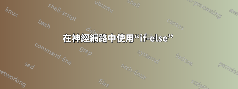
我想畫這樣的:

目前,我所擁有的是
我目前的程式碼是
\begin{figure}
\centering
\label{fig:nn2}
\begin{tikzpicture}[shorten >=1pt,->,draw=black!50, node distance=\layersep]
    \tikzstyle{every pin edge}=[<-,shorten <=1pt]
    \tikzstyle{neuron}=[circle,fill=black!25,minimum size=17pt,inner sep=0pt]
    \tikzstyle{input neuron}=[neuron, fill=green!50];
    \tikzstyle{output neuron}=[neuron, fill=red!50];
    \tikzstyle{hidden neuron}=[neuron, fill=blue!50];
    \tikzstyle{annot} = [text width=4em, text centered]

    % Draw the input layer nodes
    \foreach \name / \y in {1,...,4}
    % This is the same as writing \foreach \name / \y in {1/1,2/2,3/3,4/4}
        %\if \y in {1,2,3,4}
        \node[input neuron, pin=left:Input \#\y] (I-\name) at (0,-\y) {$x_{\name}$};
        %\else
        %\node[input neuron, pin=left:Input \#\y] (I-\name) at (0,-\y) {$x_{\name}$};
    %\node[input neuron, pin=left:Input \#4] (+1) at (0,-4) {$x_{\name}$};

    % Draw the hidden layer nodes
    \foreach \name / \y in {1,...,4}
        \path[yshift=0.5cm]
            node[hidden neuron] (H-\name) at (\layersep,-\y cm) {$h_{\name}$};

    % Draw the output layer node
    \node[output neuron,pin={[pin edge={->}]right:Output}, right of=H-3] (O) {$y_{0}$};

    % Connect every node in the input layer with every node in the
    % hidden layer.
    \foreach \source in {1,...,4}
        \foreach \dest in {1,...,4}
            \path (I-\source) edge (H-\dest);

    % Connect every node in the hidden layer with the output layer
    \foreach \source in {1,...,4}
        \path (H-\source) edge (O);

    % Annotate the layers
    \node[annot,above of=H-1, node distance=1cm] (hl) {Hidden layer};
    \node[annot,left of=hl] {Input layer};
    \node[annot,right of=hl] {Output layer};
\end{tikzpicture}
\caption{A figure shows the structure of a general neural networks model}
\end{figure}
我嘗試使用“if-else”。修改後,我的程式碼是:
\begin{figure}
\centering
\label{fig:nn2}
\begin{tikzpicture}[shorten >=1pt,->,draw=black!50, node distance=\layersep]
    \tikzstyle{every pin edge}=[<-,shorten <=1pt]
    \tikzstyle{neuron}=[circle,fill=black!25,minimum size=17pt,inner sep=0pt]
    \tikzstyle{input neuron}=[neuron, fill=green!50];
    \tikzstyle{output neuron}=[neuron, fill=red!50];
    \tikzstyle{hidden neuron}=[neuron, fill=blue!50];
    \tikzstyle{annot} = [text width=4em, text centered]

    % Draw the input layer nodes
    \foreach \name / \y in {1,...,4}
    % This is the same as writing \foreach \name / \y in {1/1,2/2,3/3,4/4}
        \if \y in {1,2,3,4}
        \node[input neuron, pin=left:Input \#\y] (I-\name) at (0,-\y) {$x_{\name}$};
        \else
        %\node[input neuron, pin=left:Input \#\y] (I-\name) at (0,-\y) {$x_{\name}$};
    %\node[input neuron, pin=left:Input \#4] (+1) at (0,-4) {$x_{\name}$};

    % Draw the hidden layer nodes
    \foreach \name / \y in {1,...,4}
        \path[yshift=0.5cm]
            node[hidden neuron] (H-\name) at (\layersep,-\y cm) {$h_{\name}$};

    % Draw the output layer node
    \node[output neuron,pin={[pin edge={->}]right:Output}, right of=H-3] (O) {$y_{0}$};

    % Connect every node in the input layer with every node in the
    % hidden layer.
    \foreach \source in {1,...,4}
        \foreach \dest in {1,...,4}
            \path (I-\source) edge (H-\dest);

    % Connect every node in the hidden layer with the output layer
    \foreach \source in {1,...,4}
        \path (H-\source) edge (O);

    % Annotate the layers
    \node[annot,above of=H-1, node distance=1cm] (hl) {Hidden layer};
    \node[annot,left of=hl] {Input layer};
    \node[annot,right of=hl] {Output layer};
\end{tikzpicture}
\caption{A figure shows the structure of a general neural networks model}
\end{figure}
但是,有一個錯誤:Extra },或忘記了 \endgroup
謝謝你!
答案1
您缺少循環體周圍的大括號和\fi關閉 if 語句的大括號。該聲明也\if無法按您的預期工作:
\if<token1><token2>(測試字元代碼是否一致)TeX 將展開隨後的宏,
\if直到找到兩個不可展開的標記。如果任一標記是控制序列,則 TeX 認為它具有字元代碼 256 和類別代碼 16,除非該控制序列的目前等效項已\let等於非活動字元標記。這樣,每個標記指定一個(字元代碼,類別代碼)對。如果字元代碼相等,則條件為真,與類別代碼無關。例如,在\def\a{*}and\let\b=*和 後\def\c{/},測試\if*\a和\if\a\b將為 true,但\if\a\c將為 false。也會\if\a\par是假的,但\if\par\let也會是真的。
(TeXbook 第 209 頁)
因此,您在第一個迭代步驟中進行比較1,i在第二個迭代步驟中進行比較,依此2類推i,始終評估為 false。相反,我檢查這是否是最後一個迭代步驟\ifnum:
\begin{figure}
\centering
\label{fig:nn2}
\begin{tikzpicture}[shorten >=1pt,->,draw=black!50, node distance=\layersep]
    \tikzstyle{every pin edge}=[<-,shorten <=1pt]
    \tikzstyle{neuron}=[circle,fill=black!25,minimum size=17pt,inner sep=0pt]
    \tikzstyle{input neuron}=[neuron, fill=green!50];
    \tikzstyle{output neuron}=[neuron, fill=red!50];
    \tikzstyle{hidden neuron}=[neuron, fill=blue!50];
    \tikzstyle{annot} = [text width=4em, text centered]
    \newcommand{\n}{4} % number of neurons per layer

    % Draw the input layer nodes
    \foreach \name / \y in {1,...,\n}{
    % This is the same as writing \foreach \name / \y in {1/1,2/2,3/3,4/4}
        \ifnum \y=\n
            \node[input neuron, pin=left:Input \#$n$] (I-\name) at (0,-\y) {$x_{n}$};
        \else
            \node[input neuron, pin=left:Input \#\y] (I-\name) at (0,-\y) {$x_{\name}$};
        \fi
    }

    % Draw the hidden layer nodes
    \foreach \name / \y in {1,...,\n}{
        \ifnum \y=\n
            \path[yshift=0.5cm] node[hidden neuron] (H-\name) at (\layersep,-\y cm) {$h_{n}$};
        \else
            \path[yshift=0.5cm] node[hidden neuron] (H-\name) at (\layersep,-\y cm) {$h_{\name}$};
        \fi
    }

    % Draw the output layer node
    \node[output neuron,pin={[pin edge={->}]right:Output}, right of=H-3] (O) {$y_{0}$};

    % Connect every node in the input layer with every node in the
    % hidden layer.
    \foreach \source in {1,...,\n}
        \foreach \dest in {1,...,\n}
            \path (I-\source) edge (H-\dest);

    % Connect every node in the hidden layer with the output layer
    \foreach \source in {1,...,\n}
        \path (H-\source) edge (O);

    % Annotate the layers
    \node[annot,above of=H-1, node distance=1cm] (hl) {Hidden layer};
    \node[annot,left of=hl] {Input layer};
    \node[annot,right of=hl] {Output layer};
\end{tikzpicture}
\caption{A figure shows the structure of a general neural networks model}
\end{figure}
但是,我不會在這裡使用任何 if :
\begin{figure}
\centering
\label{fig:nn2}
\begin{tikzpicture}[shorten >=1pt,->,draw=black!50, node distance=\layersep]
    \tikzstyle{every pin edge}=[<-,shorten <=1pt]
    \tikzstyle{neuron}=[circle,fill=black!25,minimum size=17pt,inner sep=0pt]
    \tikzstyle{input neuron}=[neuron, fill=green!50];
    \tikzstyle{output neuron}=[neuron, fill=red!50];
    \tikzstyle{hidden neuron}=[neuron, fill=blue!50];
    \tikzstyle{annot} = [text width=4em, text centered]
    \newcommand{\numberNeuronsPerLayer}{4}
    \edef\numberNeuronsPerLayerMinusOne{\number\numexpr\numberNeuronsPerLayer-1\relax}

    % Draw the input layer nodes
    \foreach \name / \y in {1,...,\numberNeuronsPerLayerMinusOne}{
    % This is the same as writing \foreach \name / \y in {1/1,2/2,3/3,4/4}
        \node[input neuron, pin=left:Input \#\y] (I-\name) at (0,-\y) {$x_{\name}$};
    }
    \node[input neuron, pin=left:Input \#$n$] (I-\numberNeuronsPerLayer) at (0,-\numberNeuronsPerLayer) {$x_{n}$};

    % Draw the hidden layer nodes
    \begin{scope}[yshift=0.5cm]
        \foreach \name / \y in {1,...,\numberNeuronsPerLayerMinusOne}{
            \path node[hidden neuron] (H-\name) at (\layersep,-\y cm) {$h_{\name}$};
        }
        \path node[hidden neuron] (H-\numberNeuronsPerLayer) at (\layersep,-\numberNeuronsPerLayer cm) {$h_{n}$};
    \end{scope}

    % Draw the output layer node
    \node[output neuron,pin={[pin edge={->}]right:Output}, right of=H-3] (O) {$y_{0}$};

    % Connect every node in the input layer with every node in the
    % hidden layer.
    \foreach \source in {1,...,\numberNeuronsPerLayer}
        \foreach \dest in {1,...,\numberNeuronsPerLayer}
            \path (I-\source) edge (H-\dest);

    % Connect every node in the hidden layer with the output layer
    \foreach \source in {1,...,\numberNeuronsPerLayer}
        \path (H-\source) edge (O);

    % Annotate the layers
    \node[annot,above of=H-1, node distance=1cm] (hl) {Hidden layer};
    \node[annot,left of=hl] {Input layer};
    \node[annot,right of=hl] {Output layer};
\end{tikzpicture}
\caption{A figure shows the structure of a general neural networks model}
\end{figure}
答案2
根據我對你的回答 問題:

\documentclass[tikz, margin=3mm]{standalone}
\usetikzlibrary{calc, chains, positioning}

\begin{document}
    \begin{tikzpicture}[shorten >=1pt,->, draw=black!50,
        node distance = 6mm and 24mm,
          start chain = going below,
every pin edge/.style = {<-,shorten <=1pt},
        neuron/.style = {circle, fill=#1,
                         minimum size=17pt, inner sep=0pt},
         annot/.style = {text width=4em, align=center}
                        ]
% Draw the input and hidden layer nodes
\ifnum\i<4
    \node[neuron=green!50, on chain,
          pin=180:Input \#\i    % if you not like to have this inputs, just erase them
          ]              (I-\i)  {$x_{\i}$};
    \node[neuron=blue!50,
      right=of I-\i]     (H-\i)  {};
\else
    \node[neuron=green!50, on chain,
          pin=180:Input \#\i    % if you not like to have this inputs, just erase them
          ]              (I-\i)  {$+1$};
    \node[neuron=blue!50,
          right=of I-\i] (H-\i)  {$+1$};
\fi
}
% Draw the output layer node
    \node[neuron=red!50,
          right=of $(H-2)!0.5!(H-3)$]  (O-1)   {};
% Connect input nodes with hidden nodes and
%  hiden nodes with output nodes with the output layer
    \foreach \i in {1,...,4}
        \foreach \j in {1,...,4}
{
    \draw (I-\i) edge (H-\j)
          (H-\j) edge (O-1);
}
    \draw (O-1) -- node[below] {$h_{w,b}(x)$} + (2,0);
% Annotate layers
\node[annot,below=of I-4.center]        {Layer 1};
\node[annot,below=of H-4.center]        {Layer 2};
\node[annot,below=of O-1 |- H-4.center] {Layer 3};
    \end{tikzpicture}
\end{document}
條件:如下來自上述 MWE
\ifnum\i<4
    action 1
\else
    action 2
\fi;
附錄: 您可以在沒有條件語句的情況下解決您的問題:
\documentclass[tikz, margin=3mm]{standalone}
\usetikzlibrary{calc, chains, positioning}

\begin{document}
    \begin{tikzpicture}[shorten >=1pt,->, draw=black!50,
        node distance = 6mm and 24mm,
          start chain = going below,
every pin edge/.style = {<-,shorten <=1pt},
        neuron/.style = {circle, fill=#1,
                         minimum size=17pt, inner sep=0pt},
         annot/.style = {text width=4em, align=center}
                        ]
% Draw the input and hyden layer nodes
\foreach \i in {1,2,3}
{
    \node[neuron=green!50, on chain,
          pin=180:Input \#\i    % if you not like to have this inputs, just erase them
          ]             (I-\i)  {$x_{\i}$};
    \node[neuron=blue!50,
      right=of I-\i]    (H-\i)     {};
}
    \node[neuron=green!50,
          pin=180:Input \#\i    % if you not like to have this inputs, just erase them
          below=of I-3
          ]              (I-4)  {$+1$};
    \node[neuron=blue!50,
          below=of H-3] (H-4)  {$+1$};
% Draw the output layer node
    \node[neuron=red!50,
          right=of $(H-2)!0.5!(H-3)$]  (O-1)   {};
% Connect input nodes with hidden nodes and
%  hiden nodes with output nodes with the output layer
    \foreach \i in {1,...,4}
        \foreach \j in {1,...,4}
{
    \draw (I-\i) edge (H-\j)
          (H-\j) edge (O-1);
}
    \draw (O-1) -- node[below] {$h_{w,b}(x)$} + (2,0);
% Annotate layers
\node[annot,below=of I-4.center]        {Layer 1};
\node[annot,below=of H-4.center]        {Layer 2};
\node[annot,below=of O-1 |- H-4.center] {Layer 3};
    \end{tikzpicture}
\end{document}
結果和以前一樣。