


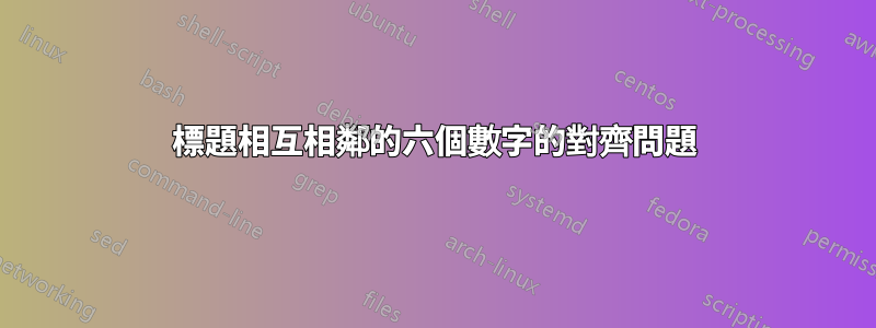
如何改進標題的對齊方式以及下圖 TikZ 的整體美感?
\documentclass[border=3pt,tikz]{report}
\usepackage{tikz}
\usepackage{float}
\usepackage{caption}
\usetikzlibrary{arrows.meta} % for arrow size
\tikzset{>=latex}
\begin{figure}[H]
        \begin{minipage}{0.16\linewidth}
            % BLOCK - NORMAL (Unloaded)
            \begin{tikzpicture}[x={(0.72cm,-0.08cm)},y={(0.40cm,0.30cm)},z={(0,1cm)}]
            \colorlet{metalcol}{blue!25!black!20!white}
            \tikzstyle{metal}=[draw=metalcol!30!black,rounded corners=0.1,top color=metalcol,bottom color=metalcol!80!black,shading angle=10]
            \tikzstyle{force}=[->,red!65!black]
            \def\W{0.7}     % side width
            \def\H{1.6}     % total height
            \def\F{0.28*\H} % force magnitude
              \draw[metal]
                (0,0,0) --++ (\W,0,0) --++ (0,0,\H) --++ (-\W,0,0) -- cycle
                (\W,0,0) --++ (0,\W,0) --++ (0,0,\H) --++ (0,-\W,0) -- cycle
                (0,0,\H) --++ (\W,0,0) --++ (0,\W,0) --++ (-\W,0,0) -- cycle;
            \end{tikzpicture}
            \caption*{Unloaded}
        \end{minipage}%
        \hfill% not: "\hspace{0.5cm}"
        \begin{minipage}{0.16\linewidth}
            % BLOCK - TENSION
            \begin{tikzpicture}[x={(0.72cm,-0.08cm)},y={(0.40cm,0.30cm)},z={(0,1cm)}]
            \colorlet{metalcol}{blue!25!black!20!white}
            \tikzstyle{metal}=[draw=metalcol!30!black,rounded corners=0.1,top color=metalcol,bottom color=metalcol!80!black,shading angle=10]
            \tikzstyle{force}=[->,red!65!black]
            \def\W{0.7}     % side width
            \def\H{1.6}     % total height
            \def\F{0.28*\H} % force magnitude
              \def\h{1.12*\H}
              \draw[force] (\W/2,\W/2,0) --++ (0,0,-\F);
              \node[below=0pt,left=0pt] at (-3.3,7.5) {$\vec{\sigma}$};
              \node[below=0pt,left=0pt] at (1.6,-1.4) {$\vec{\sigma}$};
              \draw[metal,top color=metalcol!80!blue,bottom color=metalcol!80!blue!80!black]
                (0,0,0) --++ (\W,0,0) to[out=92,in=-92]++ (0,0,\h) --++ (-\W,0,0) to[out=-84,in=84] cycle
                (\W,0,0) --++ (0,\W,0) to[out=96,in=-96]++ (0,0,\h) --++ (0,-\W,0) to[out=-92,in=92] cycle
                (0,0,\h) --++ (\W,0,0) --++ (0,\W,0) --++ (-\W,0,0) -- cycle;
              \draw[force] (\W/2,\W/2,\h) --++ (0,0,\F);
            \end{tikzpicture}
            \caption*{Tension}
        \end{minipage}%
        \hfill% not: "\hspace{0.5cm}"
        \begin{minipage}{0.16\linewidth}
            % BLOCK - COMPRESSION
            \begin{tikzpicture}[x={(0.72cm,-0.08cm)},y={(0.40cm,0.30cm)},z={(0,1cm)}]
            \colorlet{metalcol}{blue!25!black!20!white}
            \tikzstyle{metal}=[draw=metalcol!30!black,rounded corners=0.1,top color=metalcol,bottom color=metalcol!80!black,shading angle=10]
            \tikzstyle{force}=[->,red!65!black]
            \def\W{0.7}     % side width
            \def\H{1.6}     % total height
            \def\F{0.28*\H} % force magnitude
              \def\h{0.88*\H}
              \draw[force] (\W/2,\W/2,-\F) --++ (0,0,\F);
              \node[below=0pt,left=0pt] at (-2.7,6.4) {$\vec{\sigma}$};
              \node[below=0pt,left=0pt] at (1.6,-1.4) {$\vec{\sigma}$};
              \draw[metal,top color=metalcol!78!red,bottom color=metalcol!78!red!80!black]
                (0,0,0) --++ (\W,0,0) to[out=85,in=-85]++ (0,0,\h) --++ (-\W,0,0) to[out=-99,in=99] cycle
                (\W,0,0) --++ (0,\W,0) to[out=81,in=-81]++ (0,0,\h) --++ (0,-\W,0) to[out=-85,in=85] cycle
                (0,0,\h) --++ (\W,0,0) --++ (0,\W,0) --++ (-\W,0,0) -- cycle;
              \draw[force] (\W/2,\W/2,\h+\F) --++ (0,0,-\F);
            \end{tikzpicture}
            \caption*{Compression}
        \end{minipage}
        \hfill% not: "\hspace{0.5cm}"
        \begin{minipage}{0.16\linewidth}
            % BLOCK - BENDING (flexion)
            \begin{tikzpicture}[x={(0.72cm,-0.08cm)},y={(0.40cm,0.30cm)},z={(0,1cm)}]
            \colorlet{metalcol}{blue!25!black!20!white}
            \tikzstyle{metal}=[draw=metalcol!30!black,rounded corners=0.1,top color=metalcol,bottom color=metalcol!80!black,shading angle=10]
            \tikzstyle{force}=[->,red!65!black]
            \def\W{0.7}     % side width
            \def\H{1.6}     % total height
            \def\F{0.28*\H} % force magnitude
              \def\F{0.38*\H} % force magnitude
              \def\dh{0.02*\H}
              \draw[force] (0,0.3*\W,0.85*\H) --++ (-\F,0,-0.25*\F);
              \node[below=0pt,left=0pt] at (-2.7,4.8) {$\vec{M}$};
              \draw[force] (0,0.4*\W,0.13*\H) --++ (-\F,0, 0.10*\F);
              \node[below=0pt,left=0pt] at (-0.2,0.3) {$\vec{M}$};
              \draw[metal,top color=metalcol!70!orange,bottom color=metalcol!70!orange!80!black]
                (0,0,\dh) -- (\W,0,-\dh) to[out=80,in=-80] (\W,0,\H+\dh) -- (0,0,\H-\dh) to[out=-80,in=80] cycle
                (\W,0,-\dh) -- (\W,\W,-\dh) to[out=80,in=-80] (\W,\W,\H+\dh) -- (\W,0,\H+\dh) to[out=-80,in=80] cycle
                (0,0,\H-\dh) -- (\W,0,\H+\dh) -- (\W,\W,\H+\dh) -- (0,\W,\H-\dh) -- cycle;
            \end{tikzpicture}
            \caption*{Bending}
        \end{minipage}
        \hfill% not: "\hspace{0.5cm}"
        \begin{minipage}{0.16\linewidth}
            % BLOCK - TORSION
            \begin{tikzpicture}[x={(0.72cm,-0.08cm)},y={(0.40cm,0.30cm)},z={(0,1cm)}]
            \colorlet{metalcol}{blue!25!black!20!white}
            \tikzstyle{metal}=[draw=metalcol!30!black,rounded corners=0.1,top color=metalcol,bottom color=metalcol!80!black,shading angle=10]
            \tikzstyle{force}=[->,red!65!black]
            \def\W{0.7}     % side width
            \def\H{1.6}     % total height
            \def\F{0.28*\H} % force magnitude
              \def\F{0.41*\H} % force magnitude
              \draw[force] (0,0.04*\W,0.02*\H) --++ (-\F, 0.2*\F,0);
              \node[below=0pt,left=0pt] at (-0.6,0.4) {$\vec{\tau}$};
              \draw[force] (0,0.96*\W,0.98*\H) --++ (-\F,-0.2*\F,0);
              \node[below=0pt,left=0pt] at (-3,4.8) {$\vec{\tau}$};
              \draw[metal,top color=metalcol!80!green,bottom color=metalcol!80!green!80!black]
                (\W,0,0) --++ (0,\W,0) to[out=92,in=-92]++ (-\W,0,\H) -- cycle;
              \draw[metal,top color=metalcol!80!green,bottom color=metalcol!80!green!80!black]
                (0,\W,0) to[out=92,in=-92]++ (0,-\W,\H) --++ (\W,0,0) to[out=-92,in=90] cycle;
              \draw[metal,top color=metalcol!80!green,bottom color=metalcol!80!green!80!black]
                (0,0,0) --++ (\W,0,0) to[out=92,in=-92]++ (0,\W,\H) --++ (0,-\W,0) to[out=-92,in=92] cycle
                (0,0,\H) --++ (\W,0,0) --++ (0,\W,0) --++ (-\W,0,0) -- cycle;
              \draw[force] (1.02*\W,0.10*\W,0.98*\H) --++ (\F, 0.2*\F,0);
              \node[below=0pt,left=0pt] at (-0.6,4.8) {$\vec{\tau}$};
              \draw[force] (1.02*\W,0.90*\W,0.02*\H) --++ (\F,-0.2*\F,0);
              \node[below=0pt,left=0pt] at (1.61,1) {$\vec{\tau}$};
            \end{tikzpicture}
            \caption*{Torsion}
        \end{minipage}
        \hfill% not: "\hspace{0.5cm}"
        \begin{minipage}{0.16\linewidth}
            % BLOCK - SHEAR
            \begin{tikzpicture}[x={(0.72cm,-0.08cm)},y={(0.40cm,0.30cm)},z={(0,1cm)}]
            \colorlet{metalcol}{blue!25!black!20!white}
            \tikzstyle{metal}=[draw=metalcol!30!black,rounded corners=0.1,top color=metalcol,bottom color=metalcol!80!black,shading angle=10]
            \tikzstyle{force}=[->,red!65!black]
            \def\W{0.7}     % side width
            \def\H{1.6}     % total height
            \def\F{0.28*\H} % force magnitude
              \def\dw{\W}
              \def\F{0.38*\H} % force magnitude
              \draw[force] (0,\W/2,0.01*\H) --++ (-\F,0,0);
              \node[below=0pt,left=0pt] at (-0.2,5.3) {$\vec{\tau}$};
              \draw[metal,top color=metalcol!78!purple,bottom color=metalcol!78!purple!80!black]
                (0,0,0) --++ (\W,0,0) --++ (\dw,0,\H) --++ (-\W,0,0) -- cycle
                (\W,0,0) --++ (0,\W,0) --++ (\dw,0,\H) --++ (0,-\W,0) -- cycle
                (\dw,0,\H) --++ (\W,0,0) --++ (0,\W,0) --++ (-\W,0,0) -- cycle;
              \draw[force] (\W+\dw,\W/2,0.98*\H) --++ (\F,0,0);
              \node[below=0pt,left=0pt] at (-0.6,0.4) {$\vec{\tau}$};
            \end{tikzpicture}
            \caption*{Shear}
        \end{minipage}
        \vspace*{3mm}
        \caption{Most common types of material deformations}
    \end{figure}
\end{document}
這段程式碼實際上會導致以下醜陋的結果:

答案1
我認為egreg的解決方案非常優雅,但由於我已經完成了我的解決方案,所以我也將其發布。它只使用一個 TikZ 環境,但將每個區塊放在一個範圍內,因此我不必調整一堆座標。此外,我透過將範圍移動 1/6 來猜測寬度\textwidth。對於給定的 MWE,這會導致(不縮放 tikzpicture)到過滿的 hbox,但由於 MWE 本身有一個過滿的 hbox,我猜測實際textwidth允許它在不縮放的情況下工作。
\documentclass[border=3pt,tikz]{report}
\usepackage{tikz}
\usepackage{float}
\usepackage{caption}
\usetikzlibrary{arrows.meta} % for arrow size
\tikzset{>=latex}

\begin{document}

\begin{figure}[H]
    \colorlet{metalcol}{blue!25!black!20!white}
    \tikzstyle{metal}=[draw=metalcol!30!black,rounded corners=0.1,top color=metalcol,bottom color=metalcol!80!black,shading angle=10]
    \tikzstyle{force}=[->,red!65!black]
    \def\W{0.7}     % side width
    \def\H{1.6}     % total height
    \def\F{0.28*\H} % force magnitude

    \begin{tikzpicture}[scale=0.96,x={(0.72cm,-0.08cm)},y={(0.40cm,0.30cm)},z={(0,1cm)}]
        % BLOCK - NORMAL (Unloaded)
        \draw[metal]
                (0,0,0) --++ (\W,0,0) --++ (0,0,\H) --++ (-\W,0,0) -- cycle
                (\W,0,0) --++ (0,\W,0) --++ (0,0,\H) --++ (0,-\W,0) -- cycle
                (0,0,\H) --++ (\W,0,0) --++ (0,\W,0) --++ (-\W,0,0) -- cycle;

        \node[anchor=center] at (\W/2,\W/2,-1.2){Unloaded\vphantom{p}};


        % BLOCK - TENSION
        \begin{scope}[xshift=1/6*\textwidth]
                \def\h{1.12*\H}
                \draw[force] (\W/2,\W/2,0) --++ (0,0,-\F);
                \node[below=0pt,left=0pt] at (-3.3,7.5) {$\vec{\sigma}$};
            \node[below=0pt,left=0pt] at (1.6,-1.4) {$\vec{\sigma}$};
            \draw[metal,top color=metalcol!80!blue,bottom color=metalcol!80!blue!80!black]
                (0,0,0) --++ (\W,0,0) to[out=92,in=-92]++ (0,0,\h) --++ (-\W,0,0) to[out=-84,in=84] cycle
                    (\W,0,0) --++ (0,\W,0) to[out=96,in=-96]++ (0,0,\h) --++ (0,-\W,0) to[out=-92,in=92] cycle
                    (0,0,\h) --++ (\W,0,0) --++ (0,\W,0) --++ (-\W,0,0) -- cycle;
            \draw[force] (\W/2,\W/2,\h) --++ (0,0,\F);

            \node[anchor=center] at (\W/2,\W/2,-1.2){Tension\vphantom{p}};
        \end{scope}


        % BLOCK - COMPRESSION
        \begin{scope}[xshift=2/6*\textwidth]
            \def\h{0.88*\H}
                \draw[force] (\W/2,\W/2,-\F) --++ (0,0,\F);
                \node[below=0pt,left=0pt] at (-2.7,6.4) {$\vec{\sigma}$};
                \node[below=0pt,left=0pt] at (1.6,-1.4) {$\vec{\sigma}$};
                \draw[metal,top color=metalcol!78!red,bottom color=metalcol!78!red!80!black]
                    (0,0,0) --++ (\W,0,0) to[out=85,in=-85]++ (0,0,\h) --++ (-\W,0,0) to[out=-99,in=99] cycle
                    (\W,0,0) --++ (0,\W,0) to[out=81,in=-81]++ (0,0,\h) --++ (0,-\W,0) to[out=-85,in=85] cycle
                    (0,0,\h) --++ (\W,0,0) --++ (0,\W,0) --++ (-\W,0,0) -- cycle;
            \draw[force] (\W/2,\W/2,\h+\F) --++ (0,0,-\F);

            \node[anchor=center] at (\W/2,\W/2,-1.2){Compression};
        \end{scope}


        % BLOCK - BENDING (flexion)
        \begin{scope}[xshift=3/6*\textwidth]
            \def\F{0.38*\H} % force magnitude
                \def\dh{0.02*\H}
                \draw[force] (0,0.3*\W,0.85*\H) --++ (-\F,0,-0.25*\F);
                \node[below=0pt,left=0pt] at (-2.7,4.8) {$\vec{M}$};
                \draw[force] (0,0.4*\W,0.13*\H) --++ (-\F,0, 0.10*\F);
            \node[below=0pt,left=0pt] at (-0.2,0.3) {$\vec{M}$};
            \draw[metal,top color=metalcol!70!orange,bottom color=metalcol!70!orange!80!black]
                    (0,0,\dh) -- (\W,0,-\dh) to[out=80,in=-80] (\W,0,\H+\dh) -- (0,0,\H-\dh) to[out=-80,in=80] cycle
                    (\W,0,-\dh) -- (\W,\W,-\dh) to[out=80,in=-80] (\W,\W,\H+\dh) -- (\W,0,\H+\dh) to[out=-80,in=80] cycle
                    (0,0,\H-\dh) -- (\W,0,\H+\dh) -- (\W,\W,\H+\dh) -- (0,\W,\H-\dh) -- cycle;

            \node[anchor=center] at (\W/2,\W/2,-1.2){Bending};
        \end{scope}


        % BLOCK - TORSION
        \begin{scope}[xshift=4/6*\textwidth]
            \def\F{0.41*\H} % force magnitude
            \draw[force] (0,0.04*\W,0.02*\H) --++ (-\F, 0.2*\F,0);
                \node[below=0pt,left=0pt] at (-0.6,0.4) {$\vec{\tau}$};
            \draw[force] (0,0.96*\W,0.98*\H) --++ (-\F,-0.2*\F,0);
            \node[below=0pt,left=0pt] at (-3,4.8) {$\vec{\tau}$};
            \draw[metal,top color=metalcol!80!green,bottom color=metalcol!80!green!80!black]
                    (\W,0,0) --++ (0,\W,0) to[out=92,in=-92]++ (-\W,0,\H) -- cycle;
            \draw[metal,top color=metalcol!80!green,bottom color=metalcol!80!green!80!black]
                    (0,\W,0) to[out=92,in=-92]++ (0,-\W,\H) --++ (\W,0,0) to[out=-92,in=90] cycle;
                \draw[metal,top color=metalcol!80!green,bottom color=metalcol!80!green!80!black]
                (0,0,0) --++ (\W,0,0) to[out=92,in=-92]++ (0,\W,\H) --++ (0,-\W,0) to[out=-92,in=92] cycle
                (0,0,\H) --++ (\W,0,0) --++ (0,\W,0) --++ (-\W,0,0) -- cycle;
                \draw[force] (1.02*\W,0.10*\W,0.98*\H) --++ (\F, 0.2*\F,0);
                \node[below=0pt,left=0pt] at (-0.6,4.8) {$\vec{\tau}$};
                \draw[force] (1.02*\W,0.90*\W,0.02*\H) --++ (\F,-0.2*\F,0);
            \node[below=0pt,left=0pt] at (1.61,1) {$\vec{\tau}$};

            \node[anchor=center] at (\W/2,\W/2,-1.2){Torsion\vphantom{p}};
        \end{scope}


        % BLOCK - SHEAR
        \begin{scope}[xshift=5/6*\textwidth]
            \def\dw{\W}
            \def\F{0.38*\H} % force magnitude
            \draw[force] (0,\W/2,0.01*\H) --++ (-\F,0,0);
                \node[below=0pt,left=0pt] at (-0.2,5.3) {$\vec{\tau}$};
            \draw[metal,top color=metalcol!78!purple,bottom color=metalcol!78!purple!80!black]
                    (0,0,0) --++ (\W,0,0) --++ (\dw,0,\H) --++ (-\W,0,0) -- cycle
                    (\W,0,0) --++ (0,\W,0) --++ (\dw,0,\H) --++ (0,-\W,0) -- cycle
                    (\dw,0,\H) --++ (\W,0,0) --++ (0,\W,0) --++ (-\W,0,0) -- cycle;
                \draw[force] (\W+\dw,\W/2,0.98*\H) --++ (\F,0,0);
                \node[below=0pt,left=0pt] at (-0.6,0.4) {$\vec{\tau}$};

            \node[anchor=center] at (\W/2+\dw/2,\W/2,-1.2){Shear\vphantom{p}};
        \end{scope}
    \end{tikzpicture}

    \caption{Most common types of material deformations}
    \end{figure}
\end{document}
這個解決方案可能不太優雅,但它等距地傳播光束,而不是均勻地傳播光束之間的空間,以防萬一可能更喜歡。
使用 MWE 之前和之後:

答案2
我建議使用 external tabular*,這樣您就不必猜測寬度。每張圖片都位於自己的tabular環境中,因此它們將垂直對齊。
我用\footnotesizeso不超出文字寬度。也許您可以根據文件的實際文字寬度使用\small或根本不使用。
請注意,\tikzstyle幾年前已被棄用。
\documentclass{report}
\usepackage{tikz}

\usetikzlibrary{arrows.meta} % for arrow size
\tikzset{
  >=latex,
  metal/.style={
    draw=metalcol!30!black,
    rounded corners=0.1,
    top color=metalcol,
    bottom color=metalcol!80!black,
    shading angle=10,
  },
  force/.style={->,red!65!black}
}

\begin{document}

\begin{figure}[htp]
\centering\footnotesize
\setlength{\tabcolsep}{0pt}

\begin{tabular*}{\textwidth}{@{\extracolsep{\fill}}cccccc@{}}
  \begin{tabular}{@{}c@{}}
  % BLOCK - NORMAL (Unloaded)
  \begin{tikzpicture}[x={(0.72cm,-0.08cm)},y={(0.40cm,0.30cm)},z={(0,1cm)}]
    \colorlet{metalcol}{blue!25!black!20!white}
    \def\W{0.7}     % side width
    \def\H{1.6}     % total height
    \def\F{0.28*\H} % force magnitude
    \draw[metal]
      (0,0,0) --++ (\W,0,0) --++ (0,0,\H) --++ (-\W,0,0) -- cycle
      (\W,0,0) --++ (0,\W,0) --++ (0,0,\H) --++ (0,-\W,0) -- cycle
      (0,0,\H) --++ (\W,0,0) --++ (0,\W,0) --++ (-\W,0,0) -- cycle;
  \end{tikzpicture}
  \end{tabular}
&
  % BLOCK - TENSION
  \begin{tabular}{@{}c@{}}
  \begin{tikzpicture}[x={(0.72cm,-0.08cm)},y={(0.40cm,0.30cm)},z={(0,1cm)}]
    \colorlet{metalcol}{blue!25!black!20!white}
    \def\W{0.7}     % side width
    \def\H{1.6}     % total height
    \def\F{0.28*\H} % force magnitude
    \def\h{1.12*\H}
    \draw[force] (\W/2,\W/2,0) --++ (0,0,-\F);
    \node[below=0pt,left=0pt] at (-3.3,7.5) {$\vec{\sigma}$};
    \node[below=0pt,left=0pt] at (1.6,-1.4) {$\vec{\sigma}$};
    \draw[metal,top color=metalcol!80!blue,bottom color=metalcol!80!blue!80!black]
      (0,0,0) --++ (\W,0,0) to[out=92,in=-92]++ (0,0,\h) --++ (-\W,0,0) to[out=-84,in=84] cycle
      (\W,0,0) --++ (0,\W,0) to[out=96,in=-96]++ (0,0,\h) --++ (0,-\W,0) to[out=-92,in=92] cycle
      (0,0,\h) --++ (\W,0,0) --++ (0,\W,0) --++ (-\W,0,0) -- cycle;
    \draw[force] (\W/2,\W/2,\h) --++ (0,0,\F);
  \end{tikzpicture}
  \end{tabular}
&
  % BLOCK - COMPRESSION
  \begin{tabular}{@{}c@{}}
  \begin{tikzpicture}[x={(0.72cm,-0.08cm)},y={(0.40cm,0.30cm)},z={(0,1cm)}]
    \colorlet{metalcol}{blue!25!black!20!white}
    \def\W{0.7}     % side width
    \def\H{1.6}     % total height
    \def\F{0.28*\H} % force magnitude
    \def\h{0.88*\H}
    \draw[force] (\W/2,\W/2,-\F) --++ (0,0,\F);
    \node[below=0pt,left=0pt] at (-2.7,6.4) {$\vec{\sigma}$};
    \node[below=0pt,left=0pt] at (1.6,-1.4) {$\vec{\sigma}$};
    \draw[metal,top color=metalcol!78!red,bottom color=metalcol!78!red!80!black]
      (0,0,0) --++ (\W,0,0) to[out=85,in=-85]++ (0,0,\h) --++ (-\W,0,0) to[out=-99,in=99] cycle
      (\W,0,0) --++ (0,\W,0) to[out=81,in=-81]++ (0,0,\h) --++ (0,-\W,0) to[out=-85,in=85] cycle
      (0,0,\h) --++ (\W,0,0) --++ (0,\W,0) --++ (-\W,0,0) -- cycle;
    \draw[force] (\W/2,\W/2,\h+\F) --++ (0,0,-\F);
  \end{tikzpicture}
  \end{tabular}
&
  \begin{tabular}{@{}c@{}}
  % BLOCK - BENDING (flexion)
  \begin{tikzpicture}[x={(0.72cm,-0.08cm)},y={(0.40cm,0.30cm)},z={(0,1cm)}]
    \colorlet{metalcol}{blue!25!black!20!white}
    \def\W{0.7}     % side width
    \def\H{1.6}     % total height
    \def\F{0.38*\H} % force magnitude
    \def\dh{0.02*\H}
    \draw[force] (0,0.3*\W,0.85*\H) --++ (-\F,0,-0.25*\F);
    \node[below=0pt,left=0pt] at (-2.7,4.8) {$\vec{M}$};
    \draw[force] (0,0.4*\W,0.13*\H) --++ (-\F,0, 0.10*\F);
    \node[below=0pt,left=0pt] at (-0.2,0.3) {$\vec{M}$};
    \draw[metal,top color=metalcol!70!orange,bottom color=metalcol!70!orange!80!black]
      (0,0,\dh) -- (\W,0,-\dh) to[out=80,in=-80] (\W,0,\H+\dh) -- (0,0,\H-\dh) to[out=-80,in=80] cycle
      (\W,0,-\dh) -- (\W,\W,-\dh) to[out=80,in=-80] (\W,\W,\H+\dh) -- (\W,0,\H+\dh) to[out=-80,in=80] cycle
      (0,0,\H-\dh) -- (\W,0,\H+\dh) -- (\W,\W,\H+\dh) -- (0,\W,\H-\dh) -- cycle;
  \end{tikzpicture}
  \end{tabular}
&
  \begin{tabular}{@{}c@{}}
  % BLOCK - TORSION
  \begin{tikzpicture}[x={(0.72cm,-0.08cm)},y={(0.40cm,0.30cm)},z={(0,1cm)}]
    \colorlet{metalcol}{blue!25!black!20!white}
    \def\W{0.7}     % side width
    \def\H{1.6}     % total height
    \def\F{0.41*\H} % force magnitude
    \draw[force] (0,0.04*\W,0.02*\H) --++ (-\F, 0.2*\F,0);
    \node[below=0pt,left=0pt] at (-0.6,0.4) {$\vec{\tau}$};
    \draw[force] (0,0.96*\W,0.98*\H) --++ (-\F,-0.2*\F,0);
    \node[below=0pt,left=0pt] at (-3,4.8) {$\vec{\tau}$};
    \draw[metal,top color=metalcol!80!green,bottom color=metalcol!80!green!80!black]
      (\W,0,0) --++ (0,\W,0) to[out=92,in=-92]++ (-\W,0,\H) -- cycle;
    \draw[metal,top color=metalcol!80!green,bottom color=metalcol!80!green!80!black]
      (0,\W,0) to[out=92,in=-92]++ (0,-\W,\H) --++ (\W,0,0) to[out=-92,in=90] cycle;
    \draw[metal,top color=metalcol!80!green,bottom color=metalcol!80!green!80!black]
      (0,0,0) --++ (\W,0,0) to[out=92,in=-92]++ (0,\W,\H) --++ (0,-\W,0) to[out=-92,in=92] cycle
      (0,0,\H) --++ (\W,0,0) --++ (0,\W,0) --++ (-\W,0,0) -- cycle;
    \draw[force] (1.02*\W,0.10*\W,0.98*\H) --++ (\F, 0.2*\F,0);
    \node[below=0pt,left=0pt] at (-0.6,4.8) {$\vec{\tau}$};
    \draw[force] (1.02*\W,0.90*\W,0.02*\H) --++ (\F,-0.2*\F,0);
    \node[below=0pt,left=0pt] at (1.61,1) {$\vec{\tau}$};
  \end{tikzpicture}
  \end{tabular}
&
  \begin{tabular}{@{}c@{}}
  % BLOCK - SHEAR
  \begin{tikzpicture}[x={(0.72cm,-0.08cm)},y={(0.40cm,0.30cm)},z={(0,1cm)}]
    \colorlet{metalcol}{blue!25!black!20!white}
    \def\W{0.7}     % side width
    \def\H{1.6}     % total height
    \def\dw{\W}
    \def\F{0.38*\H} % force magnitude
    \draw[force] (0,\W/2,0.01*\H) --++ (-\F,0,0);
    \node[below=0pt,left=0pt] at (-0.2,5.3) {$\vec{\tau}$};
    \draw[metal,top color=metalcol!78!purple,bottom color=metalcol!78!purple!80!black]
      (0,0,0) --++ (\W,0,0) --++ (\dw,0,\H) --++ (-\W,0,0) -- cycle
      (\W,0,0) --++ (0,\W,0) --++ (\dw,0,\H) --++ (0,-\W,0) -- cycle
      (\dw,0,\H) --++ (\W,0,0) --++ (0,\W,0) --++ (-\W,0,0) -- cycle;
    \draw[force] (\W+\dw,\W/2,0.98*\H) --++ (\F,0,0);
    \node[below=0pt,left=0pt] at (-0.6,0.4) {$\vec{\tau}$};
  \end{tikzpicture}
  \end{tabular}
\\
Unloaded & Tension & Compression & Bending & Torsion & Shear
\end{tabular*}

\caption{Most common types of material deformations}

\end{figure}

\end{document}

答案3
第一步:使圖形程式碼更短,使用subfigureodsubcaption包垂直對齊子標題:
\documentclass{report}
\usepackage{subcaption}
\usepackage{tikz}
\usetikzlibrary{arrows.meta} % for arrow size
\colorlet{metalcol}{blue!25!black!20!white}

\begin{document}
    \begin{figure}[ht]
\tikzset{
    >=Straight Barb,
    x={(0.72cm,-0.08cm)},y={(0.40cm,0.30cm)},z={(0,1cm)},
    metal/.style args = {#1/#2}{draw=metalcol!30!black, rounded corners=0.1,
            top color=metalcol!#1, bottom color=metalcol!#2,
            shading angle=10},
    force/.style = {->,red!65!black}
        }
\def\W{0.7}     % side width
\def\H{1.6}     % total height
\def\F{0.28*\H} % force magnitude

\begin{subfigure}[b]{0.16\linewidth}
    \begin{tikzpicture}
%
\draw[metal=1/80!black]  %top color=metalcol,bottom color=metalcol!80!black
    (0,0,0)  --++ (\W,0,0) --++ (0,0,\H) --++ (-\W,0,0) -- cycle
    (\W,0,0) --++ (0,\W,0) --++ (0,0,\H) --++ (0,-\W,0) -- cycle
    (0,0,\H) --++ (\W,0,0) --++ (0,\W,0) --++ (-\W,0,0) -- cycle;
    \end{tikzpicture}
\caption*{Unloaded}
\end{subfigure}%
\hfill
\begin{subfigure}[b]{0.16\linewidth}
    \begin{tikzpicture}
\def\h{1.12*\H}
\draw[force] (\W/2,\W/2,0) --++ (0,0,-\F);
\node[below,left] at (-3.3,7.5) {$\vec{\sigma}$};
\node[below,left] at (1.6,-1.4) {$\vec{\sigma}$};
\draw[metal=80!blue/80!blue!80!black]
    (0,0,0) --++ (\W,0,0) to[out=92,in=-92]++ (0,0,\h) --++ (-\W,0,0) to[out=-84,in=84] cycle
    (\W,0,0) --++ (0,\W,0) to[out=96,in=-96]++ (0,0,\h) --++ (0,-\W,0) to[out=-92,in=92] cycle
    (0,0,\h) --++ (\W,0,0) --++ (0,\W,0) --++ (-\W,0,0) -- cycle;
\draw[force] (\W/2,\W/2,\h) --++ (0,0,\F);
    \end{tikzpicture}
\caption*{Tension}
\end{subfigure}%
\hfill
\begin{subfigure}[b]{0.16\linewidth}
    \begin{tikzpicture}
\def\h{0.88*\H}
\draw[force] (\W/2,\W/2,-\F) --++ (0,0,\F);
\node[below,left] at (-2.7,6.4) {$\vec{\sigma}$};
\node[below,left] at (1.6,-1.4) {$\vec{\sigma}$};
\draw[metal=78!red/78!red!80!black]
    (0,0,0) --++ (\W,0,0) to[out=85,in=-85]++ (0,0,\h) --++ (-\W,0,0) to[out=-99,in=99] cycle
    (\W,0,0) --++ (0,\W,0) to[out=81,in=-81]++ (0,0,\h) --++ (0,-\W,0) to[out=-85,in=85] cycle
    (0,0,\h) --++ (\W,0,0) --++ (0,\W,0) --++ (-\W,0,0) -- cycle;
\draw[force] (\W/2,\W/2,\h+\F) --++ (0,0,-\F);
    \end{tikzpicture}
\caption*{Compression}
\end{subfigure}
\hfill
\begin{subfigure}[b]{0.16\linewidth}
            % BLOCK - BENDING (flexion)
    \begin{tikzpicture}
\def\dh{0.02*\H}
\draw[force] (0,0.3*\W,0.85*\H) --++ (-\F,0,-0.25*\F);
\node[below,left] at (-2.7,4.8) {$\vec{M}$};
\draw[force] (0,0.4*\W,0.13*\H) --++ (-\F,0, 0.10*\F);
\node[below,left] at (-0.2,0.3) {$\vec{M}$};
\draw[metal=70!orange/70!orange!80!black]%top color=metalcol!70!orange,bottom color=metalcol!70!orange!80!black]
    (0,0,\dh) -- (\W,0,-\dh) to[out=80,in=-80] (\W,0,\H+\dh) -- (0,0,\H-\dh) to[out=-80,in=80] cycle
    (\W,0,-\dh) -- (\W,\W,-\dh) to[out=80,in=-80] (\W,\W,\H+\dh) -- (\W,0,\H+\dh) to[out=-80,in=80] cycle
    (0,0,\H-\dh) -- (\W,0,\H+\dh) -- (\W,\W,\H+\dh) -- (0,\W,\H-\dh) -- cycle;
    \end{tikzpicture}
\caption*{Bending}
\end{subfigure}
\hfill
\begin{subfigure}[b]{0.16\linewidth}
            % BLOCK - TORSION
    \begin{tikzpicture}
\def\F{0.41*\H} % force magnitude
\draw[force] (0,0.04*\W,0.02*\H) --++ (-\F, 0.2*\F,0);
\node[below,left] at (-0.6,0.4) {$\vec{\tau}$};
\draw[force] (0,0.96*\W,0.98*\H) --++ (-\F,-0.2*\F,0);
\node[below,left] at (-3,4.8) {$\vec{\tau}$};
\draw[metal=80!green/80!green!80!black]
    (\W,0,0) --++ (0,\W,0) to[out=92,in=-92]++ (-\W,0,\H) -- cycle;
\draw[metal=80!green/80!green!80!black]
    (0,\W,0) to[out=92,in=-92]++ (0,-\W,\H) --++ (\W,0,0) to[out=-92,in=90] cycle;
\draw[metal=80!green/80!green!80!black]%top
    (0,0,0) --++ (\W,0,0) to[out=92,in=-92]++ (0,\W,\H) --++ (0,-\W,0) to[out=-92,in=92] cycle
    (0,0,\H) --++ (\W,0,0) --++ (0,\W,0) --++ (-\W,0,0) -- cycle;
\draw[force] (1.02*\W,0.10*\W,0.98*\H) --++ (\F, 0.2*\F,0);
\node[below,left] at (-0.6,4.8) {$\vec{\tau}$};
\draw[force] (1.02*\W,0.90*\W,0.02*\H) --++ (\F,-0.2*\F,0);
\node[below,left] at (1.61,1) {$\vec{\tau}$};
    \end{tikzpicture}
    \caption*{Torsion}
\end{subfigure}
\hfill
\begin{subfigure}{0.16\linewidth}
            % BLOCK - SHEAR
    \begin{tikzpicture}
\def\dw{\W}
\def\F{0.38*\H} % force magnitude
\draw[force] (0,\W/2,0.01*\H) --++ (-\F,0,0);
\node[below,left] at (-0.2,5.3) {$\vec{\tau}$};
\draw[metal=78!purple/78!purple!80!black]%,top color=metalcol!78!purple,bottom color=metalcol!78!purple!80!black
    (0,0,0) --++ (\W,0,0) --++ (\dw,0,\H) --++ (-\W,0,0) -- cycle
    (\W,0,0) --++ (0,\W,0) --++ (\dw,0,\H) --++ (0,-\W,0) -- cycle
    (\dw,0,\H) --++ (\W,0,0) --++ (0,\W,0) --++ (-\W,0,0) -- cycle;
\draw[force] (\W+\dw,\W/2,0.98*\H) --++ (\F,0,0);
\node[below,left] at (-0.6,0.4) {$\vec{\tau}$};
    \end{tikzpicture}
            \caption*{Shear}
\end{subfigure}
\caption{Most common types of material deformations}
    \end{figure}
\end{document}

第二步:按用途垂直對齊影像baseline=(current bounding box.center)並將tikzpictures插入tvlr表格中。有了這個數字代碼就進一步縮短了。可能你之後:
\documentclass{report}
\usepackage{tabularray}
\usepackage{tikz}
\usetikzlibrary{arrows.meta} % for arrow size
\colorlet{metalcol}{blue!25!black!20!white}

\begin{document}
    \begin{figure}[ht]
\tikzset{
    >=Straight Barb,
    x={(0.72cm,-0.08cm)},y={(0.40cm,0.30cm)},z={(0,1cm)},
    metal/.style args = {#1/#2}{draw=metalcol!30!black, rounded corners=0.1,
            top color=metalcol!#1, bottom color=metalcol!#2,
            shading angle=10},
    force/.style = {->,red!65!black},
    baseline=(current bounding box.center)
        }
\def\W{0.7}     % side width
\def\H{1.6}     % total height
\def\F{0.28*\H} % force magnitude

    \begin{tblr}{colspec = {@{} *{6}{X[c]} @{}}}
    \begin{tikzpicture}
\draw[metal=1/80!black]
    (0,0,0)  --++ (\W,0,0) --++ (0,0,\H) --++ (-\W,0,0) -- cycle
    (\W,0,0) --++ (0,\W,0) --++ (0,0,\H) --++ (0,-\W,0) -- cycle
    (0,0,\H) --++ (\W,0,0) --++ (0,\W,0) --++ (-\W,0,0) -- cycle;
    \end{tikzpicture}
&
    \begin{tikzpicture}
\def\h{1.12*\H}
\draw[force] (\W/2,\W/2,0) --++ (0,0,-\F);
\node[below,left] at (-3.3,7.5) {$\vec{\sigma}$};
\node[below,left] at (1.6,-1.4) {$\vec{\sigma}$};
\draw[metal=80!blue/80!blue!80!black]
    (0,0,0) --++ (\W,0,0) to[out=92,in=-92]++ (0,0,\h) --++ (-\W,0,0) to[out=-84,in=84] cycle
    (\W,0,0) --++ (0,\W,0) to[out=96,in=-96]++ (0,0,\h) --++ (0,-\W,0) to[out=-92,in=92] cycle
    (0,0,\h) --++ (\W,0,0) --++ (0,\W,0) --++ (-\W,0,0) -- cycle;
\draw[force] (\W/2,\W/2,\h) --++ (0,0,\F);
    \end{tikzpicture}
&
    \begin{tikzpicture}
\def\h{0.88*\H}
\draw[force] (\W/2,\W/2,-\F) --++ (0,0,\F);
\node[below,left] at (-2.7,6.4) {$\vec{\sigma}$};
\node[below,left] at (1.6,-1.4) {$\vec{\sigma}$};
\draw[metal=78!red/78!red!80!black]
    (0,0,0) --++ (\W,0,0) to[out=85,in=-85]++ (0,0,\h) --++ (-\W,0,0) to[out=-99,in=99] cycle
    (\W,0,0) --++ (0,\W,0) to[out=81,in=-81]++ (0,0,\h) --++ (0,-\W,0) to[out=-85,in=85] cycle
    (0,0,\h) --++ (\W,0,0) --++ (0,\W,0) --++ (-\W,0,0) -- cycle;
\draw[force] (\W/2,\W/2,\h+\F) --++ (0,0,-\F);
    \end{tikzpicture}
&
    \begin{tikzpicture}
\def\dh{0.02*\H}
\draw[force] (0,0.3*\W,0.85*\H) --++ (-\F,0,-0.25*\F);
\node[below,left] at (-2.7,4.8) {$\vec{M}$};
\draw[force] (0,0.4*\W,0.13*\H) --++ (-\F,0, 0.10*\F);
\node[below,left] at (-0.2,0.3) {$\vec{M}$};
\draw[metal=70!orange/70!orange!80!black]%top color=metalcol!70!orange,bottom color=metalcol!70!orange!80!black]
    (0,0,\dh) -- (\W,0,-\dh) to[out=80,in=-80] (\W,0,\H+\dh) -- (0,0,\H-\dh) to[out=-80,in=80] cycle
    (\W,0,-\dh) -- (\W,\W,-\dh) to[out=80,in=-80] (\W,\W,\H+\dh) -- (\W,0,\H+\dh) to[out=-80,in=80] cycle
    (0,0,\H-\dh) -- (\W,0,\H+\dh) -- (\W,\W,\H+\dh) -- (0,\W,\H-\dh) -- cycle;
    \end{tikzpicture}
&
    \begin{tikzpicture}
\def\F{0.41*\H} % force magnitude
\draw[force] (0,0.04*\W,0.02*\H) --++ (-\F, 0.2*\F,0);
\node[below,left] at (-0.6,0.4) {$\vec{\tau}$};
\draw[force] (0,0.96*\W,0.98*\H) --++ (-\F,-0.2*\F,0);
\node[below,left] at (-3,4.8) {$\vec{\tau}$};
\draw[metal=80!green/80!green!80!black]
    (\W,0,0) --++ (0,\W,0) to[out=92,in=-92]++ (-\W,0,\H) -- cycle;
\draw[metal=80!green/80!green!80!black]
    (0,\W,0) to[out=92,in=-92]++ (0,-\W,\H) --++ (\W,0,0) to[out=-92,in=90] cycle;
\draw[metal=80!green/80!green!80!black]%top
    (0,0,0) --++ (\W,0,0) to[out=92,in=-92]++ (0,\W,\H) --++ (0,-\W,0) to[out=-92,in=92] cycle
    (0,0,\H) --++ (\W,0,0) --++ (0,\W,0) --++ (-\W,0,0) -- cycle;
\draw[force] (1.02*\W,0.10*\W,0.98*\H) --++ (\F, 0.2*\F,0);
\node[below,left] at (-0.6,4.8) {$\vec{\tau}$};
\draw[force] (1.02*\W,0.90*\W,0.02*\H) --++ (\F,-0.2*\F,0);
\node[below,left] at (1.61,1) {$\vec{\tau}$};
    \end{tikzpicture}
&
    \begin{tikzpicture}
\def\dw{\W}
\def\F{0.38*\H} % force magnitude
\draw[force] (0,\W/2,0.01*\H) --++ (-\F,0,0);
\node[below,left] at (-0.2,5.3) {$\vec{\tau}$};
\draw[metal=78!purple/78!purple!80!black]%,top color=metalcol!78!purple,bottom color=metalcol!78!purple!80!black
    (0,0,0) --++ (\W,0,0) --++ (\dw,0,\H) --++ (-\W,0,0) -- cycle
    (\W,0,0) --++ (0,\W,0) --++ (\dw,0,\H) --++ (0,-\W,0) -- cycle
    (\dw,0,\H) --++ (\W,0,0) --++ (0,\W,0) --++ (-\W,0,0) -- cycle;
\draw[force] (\W+\dw,\W/2,0.98*\H) --++ (\F,0,0);
\node[below=0pt,left=0pt] at (-0.6,0.4) {$\vec{\tau}$};
    \end{tikzpicture}       \\
Unloaded & Tension & Compression & Bending & Torsion & Shear
    \end{tblr}
\caption{Most common types of material deformations}
    \end{figure}
\end{document}

答案4
TikZ 矩陣:
between origins將變形塊均勻地分佈在寬度上(當然,這只在它們的寬度大致相同時才有效)。使左側(以視覺中心為中心)與右側(以視覺中心為中心)一樣寬的修剪剪切相比之下,圖向右突出很遠)。
因此,剪切圖中的節點比其他節點放置得更靠內。
您可以使用類似的方法
column sep = 2\tabcolsep來模擬環境的水平間距tabular。然後,重要的是第二行中的節點沒有 sep,以便它們緊密地位於其列中。
請注意我如何使用相同的
force路徑壓縮至於緊張但只是顛倒了箭頭提示。此
geometry套件用於顯示文字區域。
程式碼
\documentclass{report}
\usepackage{tikz}
\usepackage{float}
\usetikzlibrary{arrows.meta, calc} % for arrow size
\tikzset{
  tight matrix/.style={
    matrix, every outer matrix/.append style={
      inner sep=+0pt, outer sep=+0pt, shape=rectangle, path only}},
  material deformations diagrams/.style={
    /utils/exec=%
      \colorlet{metalcol}{blue!25!black!20!white}%
      \def\W{0.7}%     side width
      \def\H{1.6}%     total height
      \def\F{0.28*\H},%force magnitude
    metal/.style={
      rounded corners=0.1, draw=metalcol!30!black, shading angle=10,
      top color=metalcol!##1, bottom color=metalcol!##1!80!black},
    metal/.default=80!black,
    force/.style={>=Latex, ->, draw=red!65!black},
    x={(0.72cm,-0.08cm)}, y={(0.40cm,0.30cm)}, z={(0,1cm)}}}
\usepackage[showframe]{geometry}
\begin{document}
\begin{figure}[H]
\centering
\begin{tikzpicture}[material deformations diagrams,
  % to make the left side as wide as the right side
  % centered around the middle of subfigures
  trim left=($(current bounding box.east)!2!($(n3)!.5!(n4)$)$),
  % this does the same visually but doesn't warn about overfull hboxes:
  % trim left=(n1), trim right=(n6)
]
\matrix[
  tight matrix, row sep=+.7em,
  %
  % I'd suggest between origins for distributing the figures equally
  % for this, we name the nodes and use them
  % to trim the picture so that it is centered
  % we actually subtract a bit from the available width
  % because the Shear picture extrudes very much to the right
  column sep={\linewidth/6,between origins},
  %
  % The middle of the defomred blocks are roughly centered above the text:
  row 1/.append code=\tikzset{shift={(-\W/2,-\W/2)}},
  %
  % anchor = base: for vertical alignment of nodes
  % no seps:       for as tight as possible (when not *between origins*)
  % node names:    for trimming
  row 2/.append style={inner sep=+0pt, outer sep=+0pt, anchor=base,
    nodes={name=n\the\pgfmatrixcurrentcolumn}}]{
\draw[metal, top color=metalcol]
  (0,0,0)  --++ (\W,0,0) --++ (0,0,\H) --++ (-\W,0,0) -- cycle
  (\W,0,0) --++ (0,\W,0) --++ (0,0,\H) --++ (0,-\W,0) -- cycle
  (0,0,\H) --++ (\W,0,0) --++ (0,\W,0) --++ (-\W,0,0) -- cycle;
&
\def\h{1.12*\H}
\draw[force] (\W/2,\W/2,0) --++ (0,0,-\F) node[below]{$\vec{\sigma}$};
\draw[metal=80!blue]
  (0,0,0)  --++ (\W,0,0) to[out=92,in=-92]++ (0,0,\h) --++ (-\W,0,0) to[out=-84,in=84] cycle
  (\W,0,0) --++ (0,\W,0) to[out=96,in=-96]++ (0,0,\h) --++ (0,-\W,0) to[out=-92,in=92] cycle
  (0,0,\h) --++ (\W,0,0) --++ (0,\W,0) --++ (-\W,0,0) -- cycle;
\draw[force] (\W/2,\W/2,\h) --++ (0,0,\F) node[above]{$\vec{\sigma}$};
&
\def\h{0.88*\H}
\draw[force, <-] (\W/2,\W/2,0) --++ (0,0,-\F) node[below]{$\vec{\sigma}$};
\draw[metal=78!red]
  (0,0,0)  --++ (\W,0,0) to[out=85,in=-85]++ (0,0,\h) --++ (-\W,0,0) to[out=-99,in=99] cycle
  (\W,0,0) --++ (0,\W,0) to[out=81,in=-81]++ (0,0,\h) --++ (0,-\W,0) to[out=-85,in=85] cycle
  (0,0,\h) --++ (\W,0,0) --++ (0,\W,0) --++ (-\W,0,0) -- cycle;
\draw[force, <-] (\W/2,\W/2,\h) --++ (0,0,\F) node[above]{$\vec{\sigma}$};
&
\def\F{0.38*\H} % force magnitude
\def\dh{0.02*\H}
\draw[force] (0,0.3*\W,0.85*\H) --++ (-\F,0,-0.25*\F) node[left]{$\vec{M}$};
\draw[force] (0,0.4*\W,0.13*\H) --++ (-\F,0, 0.10*\F) node[left]{$\vec{M}$};
\draw[metal=70!orange]
  (0,0,\dh)    -- (\W,0,-\dh)  to[out=80,in=-80] (\W,0,\H+\dh)  -- (0,0,\H-\dh)  to[out=-80,in=80] cycle
  (\W,0,-\dh)  -- (\W,\W,-\dh) to[out=80,in=-80] (\W,\W,\H+\dh) -- (\W,0,\H+\dh) to[out=-80,in=80] cycle
  (0,0,\H-\dh) -- (\W,0,\H+\dh) -- (\W,\W,\H+\dh) -- (0,\W,\H-\dh) -- cycle;
&
\def\F{0.41*\H} % force magnitude
\draw[force] (0,0.04*\W,0.02*\H) --++ (-\F, 0.2*\F,0) node[left]{$\vec{\tau}$};
\draw[force] (0,0.96*\W,0.98*\H) --++ (-\F,-0.2*\F,0) node[left]{$\vec{\tau}$};
\draw[metal=80!green]
  (\W,0,0) --++ (0,\W,0) to[out=92,in=-92]++ (-\W,0,\H) -- cycle;
\draw[metal=80!green]
  (0,\W,0) to[out=92,in=-92]++ (0,-\W,\H) --++ (\W,0,0) to[out=-92,in=90] cycle;
\draw[metal=80!green]
  (0,0,0) --++ (\W,0,0) to[out=92,in=-92]++ (0,\W,\H) --++ (0,-\W,0) to[out=-92,in=92] cycle
  (0,0,\H) --++ (\W,0,0) --++ (0,\W,0) --++ (-\W,0,0) -- cycle;
\draw[force] (1.02*\W,0.10*\W,0.98*\H) --++ (\F, 0.2*\F,0) node[right]{$\vec{\tau}$};
\draw[force] (1.02*\W,0.90*\W,0.02*\H) --++ (\F,-0.2*\F,0) node[right]{$\vec{\tau}$};
&
\def\dw{\W}
\def\F{0.38*\H} % force magnitude
\draw[force] (0,\W/2,0.01*\H) --++ (-\F,0,0) node[above right]{$\vec{\tau}$};
\draw[metal=78!purple]
  (0,0,0) --++ (\W,0,0) --++ (\dw,0,\H) --++ (-\W,0,0) -- cycle
  (\W,0,0) --++ (0,\W,0) --++ (\dw,0,\H) --++ (0,-\W,0) -- cycle
  (\dw,0,\H) --++ (\W,0,0) --++ (0,\W,0) --++ (-\W,0,0) -- cycle;
\draw[force] (\W+\dw,\W/2,0.98*\H) --++ (\F,0,0) node[below left]{$\vec{\tau}$};
\\
\node{Unloaded}; & \node{Tension}; & \node{Compression}; & \node{Bending}; & \node{Torsion}; & \node{Shear};
\\};
\end{tikzpicture}
\caption{Most common types of material deformations}
\end{figure}
\end{document}
輸出
