


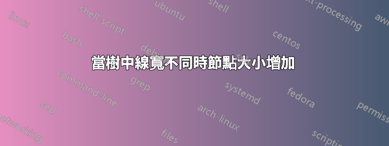
嘗試產生下圖 我將以下程式碼放在一起:
\documentclass[11pt]{book}
\usepackage{tikz}
\usepackage{tikz-qtree}
\usetikzlibrary{trees,graphs,calc,arrows.meta,positioning,decorations.pathreplacing,bending,decorations.markings,matrix,fit,patterns}
\usepackage{pgfplots}
\usepackage{xepersian}
\settextfont[Scale=1]{Tahoma}
\setlatintextfont[Scale=1]{Times New Roman}
\setdigitfont[Scale=1]{Tahoma}
\begin{document}
    \begin{figure}
        \centering
        \tikzset{
            solid node/.style={circle,draw,inner sep=1.2,fill=black},}
        \begin{tikzpicture}
            \tikzset{
                level 1/.style={level distance=12mm,sibling distance=20mm},
                level 2/.style={level distance=12mm,sibling distance=12mm},
                level 3/.style={level distance=12mm,sibling distance=6mm},
            }
            \node (r) [solid node, label = above: {$r\,$\rl{(ریشه)}}]{}
            child{node[solid node, label= left: {$a_{1}$}]{}
                child[edge from parent/.style={draw, line width=0.7mm}]{node[solid node, label = left: {$b_{1}$}]{}
                    child[edge from parent/.style={draw, thin}]{node[solid node]{}}
                    child[edge from parent/.style={draw, thin}]{node[solid node]{}}
                    child[edge from parent/.style={draw, thin}]{node[solid node]{}}
                    child[edge from parent/.style={draw, thin}]{node[solid node]{}}
            }}
            child{node[solid node, label = left:{$a_{2}$}]{}
                child[edge from parent/.style={draw, line width=0.7mm}]{node[solid node, label = left:{$b_{2}$}]{}
                    child[missing]
                    child[edge from parent/.style={draw, thin}]{node[solid node]{}}
                    child[edge from parent/.style={draw, thin}]{node[solid node]{}}
                }
            }
            child{node (a3) [solid node, label = left:{$a_{3}$}]{}
                child[edge from parent/.style={draw, line width=0.7mm}]{node (b3)[solid node, label = left:{$b_{3}$}]{}
                    child[missing]}
            }
            child{node (aq)[solid node, label = right:{$a_{q}$}]{}
                child[edge from parent/.style={draw, line width=0.7mm}]{node (bq) [solid node, label = right:{$b_{q}$}]{}
                    child[edge from parent/.style={draw, thin}]{node[solid node]{}}
                    child[edge from parent/.style={draw, thin}]{node[solid node]{}}
                    child[edge from parent/.style={draw, thin}]{node[solid node]{}}
                }
            }
            ;
            \path (a3.east) -- (aq.west) node [midway] {$\cdots$};
            \path (b3.east) -- (bq.west) node [midway] {$\cdots$};
            \tikzset{
                solid node/.style={circle,draw,inner sep=1.2,fill=black},
                no edge from this parent/.style={
                    every child/.append style={
                        edge from parent/.style={draw=none}}},
                level 3/.style={yshift=5cm},
                level 4/.style={level distance=10mm} }
            \node[right = 5 of r,align=right] {\rl{سطح $0$ (بیرونی)}} [no edge from this parent]
            child{node {\rl{سطح $1$ (درونی)}}[no edge from this parent]
                child{node {\rl{سطح $2$ (بیرونی)}} [no edge from this parent]
                    child{node {\rl{سطح $3$ (درونی)}}}
            }};
        \end{tikzpicture}
        \caption{درخت تناوبی.}
        \label{fig:3-33}
    \end{figure}
\end{document}
給出了下圖:
 正如您所看到的,節點的大小發生了變化。我怎樣才能解決這個問題?謝謝你的時間。
答案1
從節點樣式的定義中刪除draw或包含標準line width.由於您solid node在具有不同線寬的路徑上使用該樣式,因此這些節點的繪製邊框具有不同的線寬,並且其中一些看起來比其他節點大。
以下是最小化範例並添加line width=0.4pt到定義中的結果。

使用諸如 或 之類的包是明智的,但tikz-qtree更好的是,forest加載它而不使用它對您沒有任何好處。同樣,問題不依賴非拉丁腳本的使用,並且程式碼不需要序言中載入的大多數庫。
\documentclass[11pt]{book}
\usepackage{tikz}
\usetikzlibrary{positioning}
\begin{document}
\tikzset{
  solid node/.style={circle,draw,line width=0.4pt,inner sep=1.2,fill=black},}
\begin{tikzpicture}
  \tikzset{
    level 1/.style={level distance=12mm,sibling distance=20mm},
    level 2/.style={level distance=12mm,sibling distance=12mm},
    level 3/.style={level distance=12mm,sibling distance=6mm},
  }
  \node (r) [solid node, label = above: {$r\,$xxx}]{}
  child{node[solid node, label= left: {$a_{1}$}]{}
    child[edge from parent/.style={draw, line width=0.7mm}]{node[solid node, label = left: {$b_{1}$}]{}
      child[edge from parent/.style={draw, thin}]{node[solid node]{}}
      child[edge from parent/.style={draw, thin}]{node[solid node]{}}
      child[edge from parent/.style={draw, thin}]{node[solid node]{}}
      child[edge from parent/.style={draw, thin}]{node[solid node]{}}
    }}
  child{node[solid node, label = left:{$a_{2}$}]{}
    child[edge from parent/.style={draw, line width=0.7mm}]{node[solid node, label = left:{$b_{2}$}]{}
      child[missing]
      child[edge from parent/.style={draw, thin}]{node[solid node]{}}
      child[edge from parent/.style={draw, thin}]{node[solid node]{}}
    }
  }
  child{node (a3) [solid node, label = left:{$a_{3}$}]{}
    child[edge from parent/.style={draw, line width=0.7mm}]{node (b3)[solid node, label = left:{$b_{3}$}]{}
      child[missing]}
  }
  child{node (aq)[solid node, label = right:{$a_{q}$}]{}
    child[edge from parent/.style={draw, line width=0.7mm}]{node (bq) [solid node, label = right:{$b_{q}$}]{}
      child[edge from parent/.style={draw, thin}]{node[solid node]{}}
      child[edge from parent/.style={draw, thin}]{node[solid node]{}}
      child[edge from parent/.style={draw, thin}]{node[solid node]{}}
    }
  }
  ;
  \path (a3.east) -- (aq.west) node [midway] {$\cdots$};
  \path (b3.east) -- (bq.west) node [midway] {$\cdots$};
  \tikzset{
    solid node/.style={circle,draw,inner sep=1.2,fill=black},
    no edge from this parent/.style={
      every child/.append style={
        edge from parent/.style={draw=none}}},
    level 3/.style={yshift=5cm},
    level 4/.style={level distance=10mm} }
  \node[right = 5 of r,align=right] {xxx} [no edge from this parent]
  child{node {xxx}[no edge from this parent]
    child{node {xxx} [no edge from this parent]
      child{node {xxx}}
    }};
\end{tikzpicture}
\end{document}
forest(甚至tikz-qtree)將使您能夠使用更簡潔的語法和更強大的自訂功能,包括更高的自動化程度。即使簡單地定義和應用styles普通鈦kZ 會讓你的程式碼更清晰、更靈活。
例如,
\documentclass[11pt]{book}
\usepackage{forest}
\usetikzlibrary{positioning}
% ateb: https://tex.stackexchange.com/a/705271/ addaswyd o gwestiwn Arian: https://tex.stackexchange.com/q/705249/
\newcounter{forlevel}
\renewcommand* \theforlevel{\alph{forlevel}}
\forestset{%
  declare toks={level label}{},
  last level label/.style={label={right:{${#1}_{q}$}}},
  other level label/.style 2 args={label={left:{${#1}_{#2}$}}},
  fancy tree/.style={%
    for tree={
      solid node,
      tier/.option=level,
      fit=band,
    },
    before typesetting nodes={
      for nodewalk={%
        fake=root,
        last leaf,
        branch'={%
          while={%
            >On>{level}{1}%
          }{%
            parent,
            TeX={\setcounter{forlevel}{\foresteoption{level}}},
            level label/.expanded=\theforlevel,
            last level label/.option=level label,
            tikz+={\path () -- (!previous on tier) node [midway] {$\cdots$};}%
          },
          while nodewalk valid={previous on tier}{%
            previous on tier,
            TeX={\setcounter{forlevel}{\foresteoption{level}}},
            level label/.expanded=\theforlevel,
            other level label/.process={OO{level label}{n}}
          }%
        }%
      }{},
    },
    before packing={%
      tempdima/.max={> OO OO  w4+d  {s}{!u1.s}  {s sep}{!u.n children} {(##1-##2)+##3*(##4-1)} }{leaves},
      for children={minimum width=\foresteregister{tempdima},typeset node},
    },
    before drawing tree={%
      for children={minimum width=0pt,typeset node},
    },
  },
}
\tikzset{
  solid node/.style={circle,draw,line width=0.4pt,inner sep=1.2,fill=black},}
\begin{document}
\begin{forest}
  fancy tree,
  [,label={above:{${r}$ xxx}}
    [[[][][][]]]
    [[[,phantom][][]]]
    [[]]
    [[[][][]]]
  ]
  \coordinate (e) at (current bounding box.east);
  \foreach \i/\j in {!r/xxx,!rl/xxx,!rll/xxx,!rlll/xxx}
  \node [anchor=west,xshift=10pt] at (\i -| e) {\j};
\end{forest}

\end{document}