


我定義了兩種形狀:myComponent1,其中包括兩個錨點(PinA和PinB),以及myComponent2,其中包括一個錨點(PinA)。我正在尋求有關如何使用水平線直接連接的PinA指導myComponent1。下面,您將找到我的 LaTeX 程式碼以及相應的輸出。最後,我已經包含了期望的結果。PinAmyComponent2
代碼:
\documentclass{article}

\usepackage{circuitikz}

%% defining My Component 1
\pgfdeclareshape{myComponent1}{

    \anchor{center}{\pgfpointorigin}

    \savedanchor\PinA{\pgfpoint{60}{50}}
    \anchor{PinA}{\PinA}
    \savedanchor\PinB{\pgfpoint{60}{-50}}
    \anchor{PinB}{\PinB}

    \foregroundpath{

        \pgfpathrectanglecorners{\pgfpoint{-60}{-100}}{\pgfpoint{60}{100}}
        \pgfusepath{draw}

        \pgftext[right, at={\PinA}]{PIN A}
        \pgftext[right, at={\PinB}]{PIN B}
    }
}

%% defining My Component 2
\pgfdeclareshape{myComponent2}{

    \anchor{center}{\pgfpointorigin}

    \savedanchor\PinA{\pgfpoint{-60}{0}}
    \anchor{PinA}{\PinA}

    \foregroundpath{

        \pgfpathrectanglecorners{\pgfpoint{-60}{-100}}{\pgfpoint{60}{100}}
        \pgfusepath{draw}

        \pgftext[left, at={\PinA}]{PIN A}
    }
}

\begin{document}

    \begin{circuitikz}

        \draw (0,0) node[myComponent1, blue] (C1) {};
        \draw (8,5) node[myComponent2, red]  (C2) {};

        \draw (C1.PinA) -- (C2.PinA);

    \end{circuitikz}

\end{document}
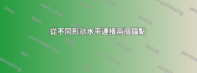
輸出:

期望的結果:

答案1
如果兩個形狀的錨點位於不同的垂直位置,則您(顯然)無法用水平線連接它們。
您可以做的是繪製第一個形狀,繪製一條水平線,然後使用錨點添加第二個形狀:
 \draw (0,0) node[myComponent1, blue] (C1) {};
 \draw (C1.PinA) -- ++(3,0) node[myComponent2, red, anchor=PinA] (C2) {};

無論如何,這沒有什麼具體的circuitikz,它是簡單的 TikZ...完整的 MWE:
\documentclass{article}
\usepackage{tikz}

%% defining My Component 1
\pgfdeclareshape{myComponent1}{
    \anchor{center}{\pgfpointorigin}
    \savedanchor\PinA{\pgfpoint{60}{50}}
    \anchor{PinA}{\PinA}
    \savedanchor\PinB{\pgfpoint{60}{-50}}
    \anchor{PinB}{\PinB}
    \foregroundpath{
        \pgfpathrectanglecorners{\pgfpoint{-60}{-100}}{\pgfpoint{60}{100}}
        \pgfusepath{draw}
        \pgftext[right, at={\PinA}]{PIN A}
        \pgftext[right, at={\PinB}]{PIN B}
    }
}
%% defining My Component 2
\pgfdeclareshape{myComponent2}{
    \anchor{center}{\pgfpointorigin}
    \savedanchor\PinA{\pgfpoint{-60}{0}}
    \anchor{PinA}{\PinA}
    \foregroundpath{
        \pgfpathrectanglecorners{\pgfpoint{-60}{-100}}{\pgfpoint{60}{100}}
        \pgfusepath{draw}
        \pgftext[left, at={\PinA}]{PIN A}
    }
}

\begin{document}
\begin{tikzpicture}
    \draw (0,0) node[myComponent1, blue] (C1) {};
    \draw (C1.PinA) -- ++(3,0) node[myComponent2, red, anchor=PinA] (C2) {};
\end{tikzpicture}
\end{document}