


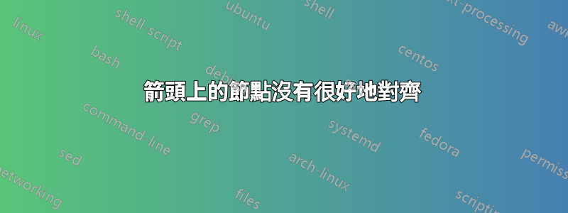
我為一個自動機編寫了 LaTeX,如下所示:

如您所看到的,從 q1 到 q3 的箭頭上的「b」位置低於從 q3 到 q2 的箭頭上的「a、b、c」。
另外,從q2到q3的邊緣上的「b」的位置比從q3到q1的箭頭上的「a、c」低。
我希望兩個節點組合能夠很好地對齊,即位於同一基線上。然而,四個都沒有必要都在同一條線上。
在我看來,我的程式碼應該自己完成此操作,但不知何故它不起作用。為什麼?
這是我的程式碼。我用註解標記了這兩個節點:
\documentclass[border=5mm]{standalone}

\usepackage{tikz}
\usetikzlibrary{automata,arrows,calc,positioning}

\begin{document}
\begin{tikzpicture}[->,node distance=25mm]
\node[state,initial,accepting] (q0) {$q_0$};
\node[state,right=of q0] (q1) {$q_1$};
\node[state,right=of q1] (q2) {$q_2$};
\node[state,below=of $(q1)!0.5!(q2)$] (q3) {$q_3$};
\node[state,accepting,right=of q2] (q4) {$q_4$};

\draw (q0) edge[loop above] node[above] {a, b} (q0);
\draw (q0) -- node[above] {b, c} ++ (q1);
\draw (q1) edge[loop above] node[above] {a, c} (q1);
\draw (q1) edge[bend left] node[above] {a, b, c} (q2);
\draw (q2) -- node[below] {a, c} ++ (q1);
\draw (q2) edge[bend left] node[right] {b} (q3);             % ! duo B
\draw (q3) -- node[above left] {a, b, c} ++ (q2);            % ! duo A
\draw (q3) edge[bend left] node[left] {a, c} (q1);           % ! duo B
\draw (q1) -- node[above right] {b} ++ (q3);                 % ! duo A
\draw (q2) edge[loop above] node[above] {a, b, c} (q2);
\draw (q2) -- node[above] {c} ++ (q4);
\draw (q1) edge[out=60,in=120] node[above] {c} (q4);
\end{tikzpicture}
\end{document}
答案1
為這些節點新增\strut或定義。我也適當地text depth改變了。above leftleftabove rightright
\documentclass[border=5mm]{standalone}

\usepackage{tikz}
\usetikzlibrary{automata,arrows,calc,positioning}

\begin{document}
\begin{tikzpicture}[->,node distance=25mm]
\node[state,initial,accepting] (q0) {$q_0$};
\node[state,right=of q0] (q1) {$q_1$};
\node[state,right=of q1] (q2) {$q_2$};
\node[state,below=of $(q1)!0.5!(q2)$] (q3) {$q_3$};
\node[state,accepting,right=of q2] (q4) {$q_4$};

\draw (q0) edge[loop above] node[above] {a, b} (q0);
\draw (q0) -- node[above] {b, c} ++ (q1);
\draw (q1) edge[loop above] node[above] {a, c} (q1);
\draw (q1) edge[bend left] node[above] {a, b, c} (q2);
\draw (q2) -- node[below] {a, c} ++ (q1);
\draw (q2) edge[bend left] node[right] {\strut b} (q3);             % ! duo B
\draw (q3) -- node[left] {\strut a, b, c} ++ (q2);            % ! duo A
\draw (q3) edge[bend left] node[left] {\strut a, c} (q1);           % ! duo B
\draw (q1) -- node[right] {\strut b} ++ (q3);                 % ! duo A
\draw (q2) edge[loop above] node[above] {a, b, c} (q2);
\draw (q2) -- node[above] {c} ++ (q4);
\draw (q1) edge[out=60,in=120] node[above] {c} (q4);
\end{tikzpicture}
\end{document}

答案2
首先,我將text height=1ex, text depth=0pt在tikzpictures 選項中新增選項,以強制所有標籤具有相同的(垂直)尺寸。
這樣做之後,問題來了
如您所見,從 q1 到 q3 的箭頭上的「b」位置低於從 q3 到 q2 的箭頭上的「a、b、c」。
另外,從q2到q3的邊緣上的「b」的位置比從q3到q1的箭頭上的「a、c」低。
被神奇地固定了。
另一個奇特的解決方案是命名重要節點,a,b,c並b根據重要節點的位置定義 的位置。那是:
\draw (q1) -- node[shift={(label-abc.west)}, xshift=-3.5mm] {b} ++ (q3);
完整程式碼:
\documentclass[border=5mm]{standalone}

\usepackage{tikz}
\usetikzlibrary{automata,arrows,calc,positioning}

\begin{document}
\begin{tikzpicture}[->,node distance=25mm, text height=1ex, text depth=0pt]
\node[state,initial,accepting] (q0) {$q_0$};
\node[state,right=of q0] (q1) {$q_1$};
\node[state,right=of q1] (q2) {$q_2$};
\node[state,below=of $(q1)!0.5!(q2)$] (q3) {$q_3$};
\node[state,accepting,right=of q2] (q4) {$q_4$};

\draw (q0) edge[loop above] node[above] {a, b} (q0);
\draw (q0) -- node[above] {b, c} ++ (q1);
\draw (q1) edge[loop above] node[above] {a, c} (q1);
\draw (q1) edge[bend left] node[above] {a, b, c} (q2);
\draw (q2) -- node[below] {a, c} ++ (q1);
\draw (q2) edge[bend left] node[right] {b} (q3);             % ! duo B
\draw (q3) -- node[above left](label-abc) {a, b, c} ++ (q2); % ! duo A
\draw (q3) edge[bend left] node[left] {a, c} (q1);           % ! duo B
\draw (q1) -- node[shift={(label-abc.west)}, xshift=-3.5mm] {b} ++ (q3); % ! duo A
\draw (q2) edge[loop above] node[above] {a, b, c} (q2);
\draw (q2) -- node[above] {c} ++ (q4);
\draw (q1) edge[out=60,in=120] node[above] {c} (q4);
\end{tikzpicture}
\end{document}

注意:同時設定text height和 ,text depth對於類似這樣的字母確實有幫助p,q,G等等。
例如:
\documentclass[border=5mm]{standalone}

\usepackage{tikz}
\usetikzlibrary{automata,arrows,calc,positioning,fit}

\begin{document}
\begin{tikzpicture}[->,node distance=25mm, text height=1ex, text depth=0pt]
\node[state,initial,accepting] (q0) {$q_0$};
\node[state,right=of q0] (q1) {$q_1$};
\node[state,right=of q1] (q2) {$q_2$};
\node[state,below=of $(q1)!0.5!(q2)$] (q3) {$q_3$};
\node[state,accepting,right=of q2] (q4) {$q_4$};

\draw (q0) edge[loop above] node[above] {a, b} (q0);
\draw (q0) -- node[above] {b, c} ++ (q1);
\draw (q1) edge[loop above] node[above] {a, c} (q1);
\draw (q1) edge[bend left] node[above] {a, b, c} (q2);
\draw (q2) -- node[below] {a, c} ++ (q1);
\draw (q2) edge[bend left] node[right] (label-g) {g} (q3);             % ! duo B
\draw (q3) -- node[draw,above left](label-abc) {a, b, c} ++ (q2); % ! duo A
\draw (q3) edge[bend left] node[left] (label-ac) {a, c} (q1);           % ! duo B
\draw (q1) -- node[draw,above right] {q} ++ (q3);                 % ! duo A
\draw (q2) edge[loop above] node[above] {a, b, c} (q2);
\draw (q2) -- node[above] {c} ++ (q4);
\draw (q1) edge[out=60,in=120] node[above] {c} (q4);

\node[draw,fit=(label-g)(label-ac)]{};
\draw (label-ac.base)--(label-g.base);
\end{tikzpicture}
\end{document}
結果:

答案3
大部分都是題外話,用於練習如何使圖表代碼更短:-)。還給出了一些額外的解釋並建議使用tikz庫“quotes”。
如其他答案中所述,您需要在邊緣標籤中定義逗號的空格。這可以透過兩種方式完成:
- 按照提議克勞迪奧·菲安德里諾:確定
text height=1ex並設定text depth=0pt。這是因為字母b和逗號分別接觸節點的頂部和底部邊框 - 如建議的@user11232:在每個傾斜邊緣標籤的節點內容處使用支柱,這使得這些節點的高度和深度相等
在下面的mwe中我遵循克勞迪奧·菲安德里諾方法,但是節點大小的定義不同,在我看來更正確。對於邊緣標籤使用edge quotes:
\documentclass[tikz, border=3mm]{standalone}
\usetikzlibrary{arrows.meta, automata,
                calc,
                positioning,
                quotes}

\begin{document}
    \begin{tikzpicture}[-Straight Barb,
node distance = 25mm,
         auto = left,
every edge quotes/.style = {inner sep=1pt,     % that labels are closer to edges
                            text height=1.5ex, % equal height,
                            text depth=2pt,    % space for commas
                                               % however this depth is not sufficient for letters as p,q, ...
                                               % for them is better 0.25ex or slightly more
                            font=\small}       % smaller letters, gives a nicer result
                        ]
\node (q0)  [state,initial,accepting]         {$q_0$};
\node (q1)  [state,right=of q0]               {$q_1$};
\node (q2)  [state,right=of q1]               {$q_2$};
\node (q3)  [state,below=of $(q1)!0.5!(q2)$]  {$q_3$};
\node (q4)  [state,accepting,right=of q2]     {$q_4$};
%
\draw   (q0) edge[loop above, "{a, b}"]     ()
        (q0) edge["{b, c}"]                 (q1)
        (q1) edge[loop above, "{a, c}"]     ()
        (q1) edge[bend left, "{a, b, c}"]   (q2)
        (q2) edge["{a, c}"]                 (q1)
        (q2) edge[loop above, "{a, b, c}"]  ()
        (q2) edge[bend left, "b"]           (q3)    % ! duo B
        (q2) edge["c"]                      (q4)
        (q3) edge["{a, b, c}"]              (q2)    % ! duo A
        (q3) edge[bend left, "{a, c}"]      (q1)    % ! duo B
        (q1) edge["b"]                      (q3)    % ! duo A
        (q1) edge[out=60,in=120, "c"]       (q4);
\end{tikzpicture}
\end{document}
