


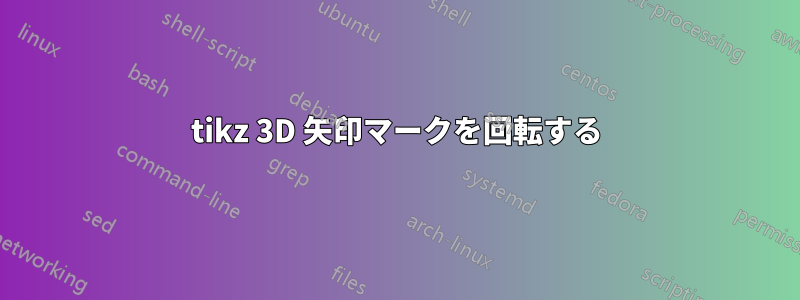
 私はインターネットのコード サンプルを使用してこれをまとめたのですが、問題があります。「a」バーの端の目盛りを地面と平行にし、線に対して垂直にしないようにしたいのです。それを実現する可能性はありますか?
\begin{tikzpicture}[cm={-1,-1,1,0,(0,0)},x=3.85mm,z=-1cm, scale=0.5]
      \draw (2,-3,-1) coordinate (x) |- (-2,3,-1) coordinate [midway] (h) coordinate (y) -- (-2,3,1) coordinate (a) -- (-2,-3,1) coordinate (z) -- (2,-3,1) edge (x) -- (2,3,1) coordinate (v) edge (h)
      -- (a)  ;
      \draw [dashed] (-2,-3,-1) coordinate (o) edge (x) edge (y) -- (z);
      \draw [->] (0,0,0) -- (2,0,0) node [midway,above] {$x$};
      \draw [->] (0,0,0) -- (0,2,0) node [midway,right] {$y$};
      \draw [->] (0,0,0) -- (0,0,2) node [midway,above] {$z$};

      \draw [|-|] (2, 3.5, -1) -- (-2, 3.5, -1) node[midway, below right] {a};
\end{tikzpicture}
答え1
おそらく水平線を自分で引いて、
\draw [|-|] (2, 3.5, -1) -- (-2, 3.5, -1) node[midway, below right] {a};
による
\draw ( 2, 3.4,-1) -- ( 2, 3.6,-1);
\draw (-2, 3.4,-1) -- (-2, 3.6,-1);
\draw ( 2, 3.5,-1) -- node[right]{a} (-2, 3.5,-1) ;
終了座標の後ではなく行演算子の後にmidway配置すると、すべての を回避できることに注意してください。node
答え2
1 つのコマンドだけで管理する方法はわかりませんが、目盛りを別々の線として描画することはできます。
\begin{tikzpicture}[cm={-1,-1,1,0,(0,0)},x=3.85mm,z=-1cm, scale=0.5]
      \draw (2,-3,-1) coordinate (x) |- (-2,3,-1) coordinate [midway] (h) coordinate (y) -- (-2,3,1) coordinate (a) -- (-2,-3,1) coordinate (z) -- (2,-3,1) edge (x) -- (2,3,1) coordinate (v) edge (h)
      -- (a)  ;
      \draw [dashed] (-2,-3,-1) coordinate (o) edge (x) edge (y) -- (z);
      \draw [->] (0,0,0) -- (2,0,0) node [midway,above] {$x$};
      \draw [->] (0,0,0) -- (0,2,0) node [midway,right] {$y$};
      \draw [->] (0,0,0) -- (0,0,2) node [midway,above] {$z$};

      \draw [-] (2, 3.5, -1) -- (-2, 3.5, -1) node[midway, below right] {a};
      \draw [-] (2, 3.75, -1) -- (2, 3.3, -1);
      \draw [-] (-2, 3.7, -1) -- (-2, 3.25, -1);
\end{tikzpicture}
この形式では、座標を変更する場合、1 行ではなく 3 行変更する必要があるため、あまり便利ではありません。それが問題になる場合は、2 つのノードと相対座標を使用して作業できるため、2 つの変数のみを変更する必要があります。
\begin{tikzpicture}[cm={-1,-1,1,0,(0,0)},x=3.85mm,z=-1cm, scale=0.5]
      \draw (2,-3,-1) coordinate (x) |- (-2,3,-1) coordinate [midway] (h) coordinate (y) -- (-2,3,1) coordinate (a) -- (-2,-3,1) coordinate (z) -- (2,-3,1) edge (x) -- (2,3,1) coordinate (v) edge (h)
      -- (a)  ;
      \draw [dashed] (-2,-3,-1) coordinate (o) edge (x) edge (y) -- (z);
      \draw [->] (0,0,0) -- (2,0,0) node [midway,above] {$x$};
      \draw [->] (0,0,0) -- (0,2,0) node [midway,right] {$y$};
      \draw [->] (0,0,0) -- (0,0,2) node [midway,above] {$z$};

    \node (a1) at (-2, 3.5, -1){};
    \node (a2) at (2, 3.5, -1){};
    \draw [-] (a1.center) -- (a2.center) node[midway, below right] {a};
    \draw [-] (a1.center) -- +(0,-0.25,0) -- +(0,0.2,0);
    \draw [-] (a2.center) -- +(0,-0.2,0) -- +(0,0.25,0);
\end{tikzpicture}
これら 2 つのサンプルはどちらも次のようになります。
