


次の MWE を検討してください。
\documentclass[a4paper]{scrartcl}

\usepackage{mathtools}
\usepackage{amssymb}

\usepackage[compatibility=false]{caption}
\usepackage[list]{subcaption}

\usepackage{fancyvrb}

\usepackage{tikz}
\usetikzlibrary{patterns, fit, positioning, calc, shapes.arrows}

\usepackage[active, tightpage, floats, displaymath]{preview}

\mathtoolsset{%
  mathic=true
}

% Vectors and matrices
\renewcommand*{\vec}[1]{\mathbf{#1}}
\newcommand{\mat}[1]{\mathbf{#1}}
\newcommand{\trans}{\intercal}

% Operators
\DeclareMathOperator{\rank}{rank}
\DeclareMathOperator*{\argmin}{arg\,min}
\DeclareMathOperator*{\argmax}{arg\,max}

\begin{document}
\begin{figure}
  \centering
  \captionsetup[subfigure]{margin={2.5cm, 0cm}}
  \begin{subfigure}[b]{0.60\textwidth}
    \centering
    \begin{tikzpicture}[>=latex, shorten >=2pt, shorten <=2pt]
      \node[draw, rectangle, label=below:the] (the) {\(\mat W\)};
      \node[draw, rectangle, right=of the, label=below:cat] (cat) {\(\mat W\)};
      \node[draw, rectangle, right=of cat, label=below:sat] (sat) {\(\mat W\)};

      \node[draw, rectangle, fit=(the.west) (the.east), pattern=vertical lines, above=of the] (in_the) {};
      \node[draw, rectangle, fit=(cat.west) (cat.east), pattern=vertical lines, above=of cat] (in_cat) {};
      \node[draw, rectangle, fit=(sat.west) (sat.east), pattern=vertical lines, above=of sat] (in_sat) {};

      \node[draw, rectangle, fit={($(cat.west) + (-8pt,0pt)$) ($(cat.east) + (8pt,0pt)$)}, pattern=vertical lines, above=2cm of cat] (in) {};
      \node[draw, rectangle, above=of in, label=above:mat] (out) {\(\vec b\), \(\mat U\)};

      \node[left=of the, outer sep=0] (embed) {embed};
      \node[above=2cm of embed, outer sep=0] (concatenate) {concatenate};
      \node[above=1cm of concatenate, outer sep=0] {softmax};

      \foreach \word in {the, cat, sat}{%
        \draw[->] (\word) -- (in_\word);
        \draw[->] (in_\word) -- (in);
      }

      \draw[->] (in) -- (out);
    \end{tikzpicture}
    \caption{CBOW model}\label{fig:cbow}
  \end{subfigure}
  \captionsetup[subfigure]{margin={0cm,0cm}}
  \begin{subfigure}[b]{0.35\textwidth}
    \centering
    \begin{tikzpicture}[>=latex, shorten >=2pt, shorten <=2pt]
      \node[draw, rectangle, label=below:cat] (cat) {\(\mat W\)};
      \node[draw, rectangle, fit=(cat.west) (cat.east), pattern=vertical lines, above=of cat] (in) {};
      \node[draw, rectangle, above=2cmof in, label=above:on] (on) {\(\vec b\), \(\mat U\)};
      \node[draw, rectangle, left=of on, label=above:sat] (sat) {\(\vec b\), \(\mat U\)};
      \node[draw, rectangle, right=of on, label=above:the] (the) {\(\vec b\), \(\mat U\)};

      \draw[->] (cat) -- (in);
      \foreach \word in {sat, on, the}{%
        \draw[->] (in) -- (\word);
      }
    \end{tikzpicture}
    \caption{Skip\=/gram model}\label{fig:sg}
  \end{subfigure}
  \caption{\protect\Verb+Word2Vec+ with vocabulary size \(V\), context
    size \(C\), and embedding size \(N\)}
\end{figure}
\end{document}

%%% Local Variables:
%%% mode: latex
%%% TeX-master: t
%%% End:
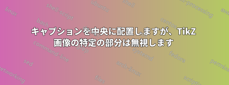
タイプセットは次のようになります:

ご覧のとおり、私は を使用して「(a) CBOW モデル」キャプションを「中央揃え」にしました\captionsetup[subfigure]{margin={2.5cm, 0cm}}。私の質問は、これを行わなくてもよいようにすることは可能でしょうか? または、少なくとも何らかの方法で、キャプションをオフセットするために必要な正しい幅を計算することはできますか?
答え1
TikZ で を使用する\useasboundingboxと、画像のサイズを設定できます。TikZ は、画像のサイズを計算するために、そのコマンドの後のすべてを無視します。 を(current bounding box)使用すると、これまでの画像のサイズを参照できます。線の前に、用紙サイズにカウントされるすべてのものを描画する限り、\useasboundingbox (current bounding box)画像は希望のサイズになります。
subfigureさらに、左側の重なりを可能にするために、空白が必要です。したがって、最初にする必要があります。もちろん、左側 (つまり、中央) のサブ図の幅を調整する必要があります。
\documentclass[a4paper]{scrartcl}

\usepackage{mathtools}
\usepackage{amssymb}

\usepackage[compatibility=false]{caption}
\usepackage[list]{subcaption}

\usepackage{fancyvrb}

\usepackage{tikz}
\usetikzlibrary{patterns, fit, positioning, calc, shapes.arrows}

\usepackage[active, tightpage, floats, displaymath]{preview}

\mathtoolsset{%
  mathic=true
}

% Vectors and matrices
\renewcommand*{\vec}[1]{\mathbf{#1}}
\newcommand{\mat}[1]{\mathbf{#1}}
\newcommand{\trans}{\intercal}

% Operators
\DeclareMathOperator{\rank}{rank}
\DeclareMathOperator*{\argmin}{arg\,min}
\DeclareMathOperator*{\argmax}{arg\,max}

\begin{document}
\begin{figure}
  \centering
% no longer needed
%  \captionsetup[subfigure]{margin={2.5cm, 0cm}}
  %empty subfugure to allow for overlap to the left
  \begin{subfigure}[b]{0.15\textwidth}
  \mbox{}
  \end{subfigure}
  \begin{subfigure}[b]{0.40\textwidth}
    \centering
    \begin{tikzpicture}[>=latex, shorten >=2pt, shorten <=2pt]
      \node[draw, rectangle, label=below:the] (the) {\(\mat W\)};
      \node[draw, rectangle, right=of the, label=below:cat] (cat) {\(\mat W\)};
      \node[draw, rectangle, right=of cat, label=below:sat] (sat) {\(\mat W\)};

      \node[draw, rectangle, fit=(the.west) (the.east), pattern=vertical lines, above=of the] (in_the) {};
      \node[draw, rectangle, fit=(cat.west) (cat.east), pattern=vertical lines, above=of cat] (in_cat) {};
      \node[draw, rectangle, fit=(sat.west) (sat.east), pattern=vertical lines, above=of sat] (in_sat) {};

      \node[draw, rectangle, fit={($(cat.west) + (-8pt,0pt)$) ($(cat.east) + (8pt,0pt)$)}, pattern=vertical lines, above=2cm of cat] (in) {};
      \node[draw, rectangle, above=of in, label=above:mat] (out) {\(\vec b\), \(\mat U\)};

      % set the picture size to everything drawn so far
      \useasboundingbox (current bounding box);

      % not taken into account for the picture size
      \node[left=of the, outer sep=0] (embed) {embed};
      \node[above=2cm of embed, outer sep=0] (concatenate) {concatenate};
      \node[above=1cm of concatenate, outer sep=0] {softmax};

      % this belongs to the main part, but it doesn't increase its size
      % otherwise it must be moved before \useasboundingbox
      \foreach \word in {the, cat, sat}{%
        \draw[->] (\word) -- (in_\word);
        \draw[->] (in_\word) -- (in);
      }

      \draw[->] (in) -- (out);
    \end{tikzpicture}
    \caption{CBOW model}\label{fig:cbow}
  \end{subfigure}
% no longer needed
%  \captionsetup[subfigure]{margin={0cm,0cm}}
  \begin{subfigure}[b]{0.35\textwidth}
    \centering
    \begin{tikzpicture}[>=latex, shorten >=2pt, shorten <=2pt]
      \node[draw, rectangle, label=below:cat] (cat) {\(\mat W\)};
      \node[draw, rectangle, fit=(cat.west) (cat.east), pattern=vertical lines, above=of cat] (in) {};
      \node[draw, rectangle, above=2cmof in, label=above:on] (on) {\(\vec b\), \(\mat U\)};
      \node[draw, rectangle, left=of on, label=above:sat] (sat) {\(\vec b\), \(\mat U\)};
      \node[draw, rectangle, right=of on, label=above:the] (the) {\(\vec b\), \(\mat U\)};

      \draw[->] (cat) -- (in);
      \foreach \word in {sat, on, the}{%
        \draw[->] (in) -- (\word);
      }
    \end{tikzpicture}
    \caption{Skip\=/gram model}\label{fig:sg}
  \end{subfigure}
  \caption{\protect\Verb+Word2Vec+ with vocabulary size \(V\), context
    size \(C\), and embedding size \(N\)}
\end{figure}
\end{document}
答え2
これは、私の元の(比較的)単純な答えよりも(比較的)単純ではない方法です。元の答えは、もう少し柔軟性があり、ほんの少しだけよくテストされています。etoolboxと が必要ですxparse。(必要に応じて後者を簡単に省略できますが、便利です。)
設定したとおり、これによりすべての
tikzpicture環境が変更されます。必要に応じて、マクロを含めるように拡張することもできます
\tikz。グローバルな影響が望ましくない場合は、
every picture定義を削除し、mark outオプションの引数で を使用するだけですtikzpicture。
左側、右側、両方、またはどちらでもない素材の調整が可能です。
MWE に基づく単純なケースの唯一の要件は、キャプションを配置するために\tikzmarkerwest使用する画像の部分の左側をマークする画像内のポイントに挿入することです\caption。画像でマクロをまったく使用しない場合は、画像が完成したときに、コードは画像の境界ボックスの左側に戻ります。これは、例の 2 番目の部分で発生しますsubfigure。
最初のコードsubfigureは再配置され、\caption無視する必要があるものはすべて画像の最初の部分の後に来ます。\tikzmarkerwest次に、この時点で左側をマークするために挿入されます。
...
      \foreach \word in {the, cat, sat}{%
        \draw[->] (\word) -- (in_\word);
        \draw[->] (in_\word) -- (in);
      }
      \draw[->] (in) -- (out);
配置に使用するものはこれですべてなので\caption、今度は画像の左側をマークします。
\tikzmarkerwest
ここで、その点の左側にあるものを配置します。これは\caption無視する必要があります。
      \node[left=of the, outer sep=0] (embed) {embed};
      \node[above=2cm of embed, outer sep=0] (concatenate) {concatenate};
      \node[above=1cm of concatenate, outer sep=0] {softmax};
ここで、写真を完成させ、通常どおりキャプションとラベルを追加します。
    \end{tikzpicture}
    \caption{CBOW model}\label{fig:cbow}

右側の資料については、\tikzmarkereastの代わりに、または とともに を使用できます\tikzmarkerwest。
場合によっては、このように画像内のコードを並べ替えるのは不便または不可能です。必要な順序で簡単に描画できないか、まったく描画できません。このため、オプションの引数\tikzmarkereastを\tikzmarkerwestサポートします。指定する場合は、通常の座標と同様に、丸括弧で囲んだ座標にする必要があります。この場合、キャプションを配置するときに、指定した座標の右または左にあるものはすべて無視されます。
これをサポートするコードは、\tikzmarkerwest次のようにマクロを定義します。
\NewDocumentCommand \tikzmarkerwest { D () {current bounding box.west} } {%
  \coordinate (tikz marker west) at (#1);
  \let\tikzmarkerwestdefault\relax
}
これにより、適切な場所に座標が作成されます(tikz marker west)。その後、\tikzmarkerwestdefault何も正常に実行されないことが確認されます。
\tikzmarkereast同じように定義されます。
\NewDocumentCommand \tikzmarkereast { D () {current bounding box.east} } {%
  \coordinate (tikz marker east) at (#1);
  \let\tikzmarkereastdefault\relax
}
確認して\tikzmarkerwestdefault定義\tikzmarkereastします。デフォルトでは何もしません。
\NewDocumentCommand \tikzmarkerwestdefault {} {}
\NewDocumentCommand \tikzmarkereastdefault {} {}
さて、TiけZコード。
\tikzset{%
このスタイルはmark out、環境へのオプションの引数で指定された場合は現在の画像の先頭と末尾で実行されるコードを追加し、以下のように構成されている場合はすべての画像で実行されるコードを追加します。
  mark out/.style={%
    execute at begin picture={%
      \RenewDocumentCommand \tikzmarkerwestdefault {}
      {%
        \coordinate (tikz marker west) at (current bounding box.west);
      }%
      \RenewDocumentCommand \tikzmarkereastdefault {}
      {%
        \coordinate (tikz marker east) at (current bounding box.east);
      }%
    },
これにより、マクロ\tikzmarkerwestdefaultとマクロが再定義され、現在の境界ボックスの左側と右側に座標と\tikzmarkereastdefaultが作成されます。これらは単なる定義であり、デフォルトの空のものを上書きします。実際にはまだ座標は作成されません。(tikz marker west)(tikz marker east)
    execute at end picture={%
      \tikzmarkerwestdefault
      \tikzmarkereastdefault
画像の最後に、 を実行します\tikzmarkerwestdefault。 が\tikzmarkerwest画像内で呼び出された場合、これは何も正常に実行されません。それ以外の場合は、現在の境界ボックスの左側にマーカーが作成されます。これが画像の最終的な境界ボックスです。 の場合も同様です\tikzmarkereastdefault。
\path let \p1=(tikz marker west), \p2=(current bounding box.west), \n1={\x1-\x2} in \pgfextra{\xdef\myadjustwest{\n1}} ;
xこれは、座標の部分(tikz marker west)とx現在の境界ボックスの左側の座標の部分との差を計算します。通常、これは 0pt になります。ただし、\tikzmarkerwestが呼び出された場合は、マーカー ノードから現在の境界ボックスの左側までの距離が 0 以外になる可能性があります。(実際、マクロが呼び出された場合は、それがマクロを使用する唯一の理由であるため、おそらくそうなるでしょう。)
(tikz marker east)ここで、現在の境界ボックスの右側に対しても同じことを行います。
      \path let \p1=(tikz marker east), \p2=(current bounding box.east), \n1={\x2-\x1} in \pgfextra{\xdef\myadjusteast{\n1}} ;
    },
  },


  every picture/.style={mark out},
この行はmark outすべてのTiにスタイルを適用しますけZ 画像。問題が発生する場合は、これを削除して、mark out必要な画像に追加してください。
}
\newlength\myadjustwest
\newlength\myadjusteast
\myadjustwest必ず、利用可能であることを確認してください\myadjusteast。
\AfterEndEnvironment{tikzpicture}{%
  \captionsetup{margin={\myadjustwest,\myadjusteast}}%
}{\typeout{OK!}}{\typeout{Oh, no!}}
これは、すべての環境の終了を適応させて、tikzpictureを正しく変更します。これを使用する場合は、と\captionの代わりに、意味のあるメッセージを自分で置き換える必要があります。OK!Oh, no!
次の例のセットは、基本的な可能性を示しています。たとえば、影付きの四角形を基準にしてキャプションを配置したい場合、四角形の一部を影付きにし、次に別の部分を、さらに別の部分を影付きにして、各段階の間に境界ボックスを適切にマークすることは (まったく簡単ではありません)。したがって、この場合は、および\tikzmarkerwest/またはのオプション引数を使用して\tikzmarkereast、可視光スペクトルの赤の端、青の端、および中央から左の中間のビットに焦点を合わせたキャプションの位置を取得します。
レッドの場合...
...
      \shade [shading=wave, shading angle=90] (0,0) rectangle ++(\linewidth,1) coordinate [pos=.4] (r);
      \tikzmarkereast(r)
...
ブルースのために...
...
      \shade [shading=wave, shading angle=90] (0,0) rectangle ++(\linewidth,1) coordinate [pos=.6] (b);
      \tikzmarkerwest(b)
...
内臓に関しては…
...
      \shade [shading=wave, shading angle=90] (0,0) rectangle ++(\linewidth,1) coordinate [pos=.1] (a) coordinate [pos=.5] (b);
      \tikzmarkereast(b)
      \tikzmarkerwest(a)
...

完全なコード:
% arara: pdflatex
\pdfminorversion=7
% ateb: https://tex.stackexchange.com/a/377652/ addaswyd o gwestiwn d125q: https://tex.stackexchange.com/q/377476/
\documentclass[a4paper]{scrartcl}
\usepackage{mathtools,amssymb}
\usepackage[compatibility=false]{caption}
\usepackage[list]{subcaption}
\usepackage{fancyvrb,tikz,etoolbox,xparse}
\usetikzlibrary{patterns, fit, positioning, calc}
\usepackage[active, tightpage, floats, displaymath]{preview}
\mathtoolsset{%
  mathic=true
}
\NewDocumentCommand \tikzmarkerwest { D () {current bounding box.west} } {%
  \coordinate (tikz marker west) at (#1);
  \let\tikzmarkerwestdefault\relax
}
\NewDocumentCommand \tikzmarkerwestdefault {} {}
\NewDocumentCommand \tikzmarkereast { D () {current bounding box.east} } {%
  \coordinate (tikz marker east) at (#1);
  \let\tikzmarkereastdefault\relax
}
\NewDocumentCommand \tikzmarkereastdefault {} {}
\tikzset{%
  mark out/.style={%
    execute at begin picture={%
      \RenewDocumentCommand \tikzmarkerwestdefault {}
      {%
        \coordinate (tikz marker west) at (current bounding box.west);
      }%
      \RenewDocumentCommand \tikzmarkereastdefault {}
      {%
        \coordinate (tikz marker east) at (current bounding box.east);
      }%
    },
    execute at end picture={%
      \tikzmarkerwestdefault
      \tikzmarkereastdefault
      \path let \p1=(tikz marker west), \p2=(current bounding box.west), \n1={\x1-\x2} in \pgfextra{\xdef\myadjustwest{\n1}} ;
      \path let \p1=(tikz marker east), \p2=(current bounding box.east), \n1={\x2-\x1} in \pgfextra{\xdef\myadjusteast{\n1}} ;
    },
  },
  every picture/.style={mark out},
}
\newlength\myadjustwest
\newlength\myadjusteast
\AfterEndEnvironment{tikzpicture}{%
  \captionsetup{margin={\myadjustwest,\myadjusteast}}%
}{\typeout{OK!}}{\typeout{Oh, no!}}

% for the examples
\definecolor{wave start}{wave}{380}
\definecolor{wave violet}{wave}{400}
\definecolor{wave indigo}{wave}{445}
\definecolor{wave blue}{wave}{475}
\definecolor{wave green}{wave}{510}
\definecolor{wave yellow}{wave}{570}
\definecolor{wave orange}{wave}{590}
\definecolor{wave red}{wave}{650}
\definecolor{wave end}{wave}{780}
\pgfdeclareverticalshading{wave}{100bp}{% manual 1088; xcolor manual; does not work to use wave model directly (?); https://science-edu.larc.nasa.gov/EDDOCS/Wavelengths_for_Colors.html
  color(0bp)=(wave start);
  color(25bp)=(wave start);
  color(27bp)=(wave violet);% 400 nm
  color(33bp)=(wave indigo);% 445nm
  color(37bp)=(wave blue);% 475nm
  color(41bp)=(wave green);% 510nm
  color(49bp)=(wave yellow);% 570nm
  color(51bp)=(wave orange);% 590nm
  color(59bp)=(wave red);% 650nm
  color(75bp)=(wave end);% 780nm
  color(100bp)=(wave end)
}
\begin{document}
\begin{figure}
  \centering
  \begin{subfigure}[b]{0.60\textwidth}
    \centering
    \begin{tikzpicture}[>=latex, shorten >=2pt, shorten <=2pt]
      \node[draw, label=below:the] (the) {\(\mathbf{W}\)};
      \node[draw, right=of the, label=below:cat] (cat) {\(\mathbf{W}\)};
      \node[draw, right=of cat, label=below:sat] (sat) {\(\mathbf{W}\)};
      \node[draw, fit=(the.west) (the.east), pattern=vertical lines, above=of the] (in_the) {};
      \node[draw, fit=(cat.west) (cat.east), pattern=vertical lines, above=of cat] (in_cat) {};
      \node[draw, fit=(sat.west) (sat.east), pattern=vertical lines, above=of sat] (in_sat) {};
      \node[draw, fit={($(cat.west) + (-8pt,0pt)$) ($(cat.east) + (8pt,0pt)$)}, pattern=vertical lines, above=2cm of cat] (in) {};
      \node[draw, above=of in, label=above:mat] (out) {\(\mathbf{b}\), \(\mathbf{U}\)};
      \foreach \word in {the, cat, sat}{%
        \draw[->] (\word) -- (in_\word);
        \draw[->] (in_\word) -- (in);
      }
      \draw[->] (in) -- (out);
      \tikzmarkerwest
      \node[left=of the, outer sep=0] (embed) {embed};
      \node[above=2cm of embed, outer sep=0] (concatenate) {concatenate};
      \node[above=1cm of concatenate, outer sep=0] {softmax};
    \end{tikzpicture}
    \caption{CBOW model}\label{fig:cbow}
  \end{subfigure}
  \begin{subfigure}[b]{0.35\textwidth}
    \centering
    \begin{tikzpicture}[>=latex, shorten >=2pt, shorten <=2pt]
      \node[draw, label=below:cat] (cat) {\(\mathbf{W}\)};
      \node[draw, fit=(cat.west) (cat.east), pattern=vertical lines, above=of cat] (in) {};
      \node[draw, above=2cmof in, label=above:on] (on) {\(\mathbf{b}\), \(\mathbf{U}\)};
      \node[draw, left=of on, label=above:sat] (sat) {\(\mathbf{b}\), \(\mathbf{U}\)};
      \node[draw, right=of on, label=above:the] (the) {\(\mathbf{b}\), \(\mathbf{U}\)};
      \draw[->] (cat) -- (in);
      \foreach \word in {sat, on, the}{%
        \draw[->] (in) -- (\word);
      }
    \end{tikzpicture}
    \caption{Skip\=/gram model}\label{fig:sg}
  \end{subfigure}
  \caption{\protect\Verb+Word2Vec+ with vocabulary size \(V\), context size \(C\), and embedding size \(N\)}
\end{figure}

\begin{figure}
  \centering
  \begin{subfigure}{.33\linewidth}
    \centering
    \begin{tikzpicture}
      \shade [shading=wave, shading angle=90] (0,0) rectangle ++(\linewidth,1) coordinate [pos=.4] (r);
      \tikzmarkereast(r)
    \end{tikzpicture}
    \caption{Reds.}
  \end{subfigure}\hfill
  \begin{subfigure}{.33\linewidth}
    \centering
    \begin{tikzpicture}
      \shade [shading=wave, shading angle=90] (0,0) rectangle ++(\linewidth,1) coordinate [pos=.6] (b);
      \tikzmarkerwest(b)
    \end{tikzpicture}
    \caption{Blues.}
  \end{subfigure}\hfill
  \begin{subfigure}{.33\linewidth}
    \centering
    \begin{tikzpicture}
      \shade [shading=wave, shading angle=90] (0,0) rectangle ++(\linewidth,1) coordinate [pos=.1] (a) coordinate [pos=.5] (b);
      \tikzmarkereast(b)
      \tikzmarkerwest(a)
    \end{tikzpicture}
    \caption{Innards.}
  \end{subfigure}\par
  \caption{Main figure}
\end{figure}
\end{document}
答え3
まず、最初の回答は編集しませんでした。そのままでも一部の人にとっては役立つかもしれないからです。
この新しい回答は、キャプションの余白を計算します。このために、プリアンブルにいくつかのマクロがあります。そして、3 つのコマンドを配置する必要があります。これらはすべて引数なしです。
画像では、メイン部分 (つまり、キャプションを中央に配置する部分) を最初に描画する必要があります。次に\pgfremembermainx挿入する必要があります。これまでの最も外側の x 位置を記憶するために座標を設定します。その後、メイン部分の左と右に重なる部分を描画する必要があります。
の直前、最後に\end{tikzpicture}コマンド\pgfgetoverlapを配置する必要があります。このコマンドは、両側への重なり (メイン部分に対する) を計算し、寸法レジスタとに格納します\overlapleft。\overlaprightどちらもグローバルに設定されるため、 の後に使用できます。tikzpicture注: の後に描画されたものはすべて、\pgfgetoverlap重なりの計算には考慮されません。
そして最後に、tikzpictureとキャプションの間に で余白を設定します\captionsetmargins。 環境内にあるため、その効果はローカルですsubfigure。 オプションの引数 ( ) はここでは使用できないため、すべてのキャプションの余白を設定することになるため、環境外では使用しないでください。[subfigure]もちろん、これは画像の後でのみ機能します。画像の前では重なりが不明だからです。
\documentclass[a4paper]{scrartcl}

\usepackage{mathtools}
\usepackage{amssymb}

\usepackage[compatibility=false]{caption}
\usepackage[list]{subcaption}

\usepackage{fancyvrb}

\usepackage{tikz}
\usetikzlibrary{patterns, fit, positioning, calc, shapes.arrows}

\usepackage[active, tightpage, floats, displaymath]{preview}

\mathtoolsset{%
  mathic=true
}

% Vectors and matrices
\renewcommand*{\vec}[1]{\mathbf{#1}}
\newcommand{\mat}[1]{\mathbf{#1}}
\newcommand{\trans}{\intercal}

% Operators
\DeclareMathOperator{\rank}{rank}
\DeclareMathOperator*{\argmin}{arg\,min}
\DeclareMathOperator*{\argmax}{arg\,max}

%---------------------------------------------------------------------
% code for automatic setting of caption margins
\makeatletter
\newdimen\overlapleft
\newdimen\overlapright

\newcommand{\pgfremembermainx}{%
    \coordinate (main west) at (current bounding box.west);
    \coordinate (main east) at (current bounding box.east);
}
\newcommand{\pgfgetoverlap}{%
    \pgfextractx{\@tempdima}{%
        \pgfpointdiff{\pgfpointanchor{current bounding box}{west}}%
                     {\pgfpointanchor{main west}{center}}%
    }%
    \global\overlapleft=\@tempdima
    \pgfextractx{\@tempdima}{%
        \pgfpointdiff{\pgfpointanchor{main east}{center}}%
                     {\pgfpointanchor{current bounding box}{east}}%
    }%
    \global\overlapright=\@tempdima
}
\newcommand{\captionsetmargins}{%
    % no additional calculation required here
    \captionsetup{margin={\overlapleft,\overlapright}}%
}
\makeatother
%---------------------------------------------------------------------

\begin{document}
\begin{figure}
  \centering
% not needed here
%  \captionsetup[subfigure]{margin={2.5cm, 0cm}}
  \begin{subfigure}[b]{0.60\textwidth}
    \centering
    \begin{tikzpicture}[>=latex, shorten >=2pt, shorten <=2pt]
      \node[draw, rectangle, label=below:the] (the) {\(\mat W\)};
      \node[draw, rectangle, right=of the, label=below:cat] (cat) {\(\mat W\)};
      \node[draw, rectangle, right=of cat, label=below:sat] (sat) {\(\mat W\)};

      \node[draw, rectangle, fit=(the.west) (the.east), pattern=vertical lines, above=of the] (in_the) {};
      \node[draw, rectangle, fit=(cat.west) (cat.east), pattern=vertical lines, above=of cat] (in_cat) {};
      \node[draw, rectangle, fit=(sat.west) (sat.east), pattern=vertical lines, above=of sat] (in_sat) {};

      \node[draw, rectangle, fit={($(cat.west) + (-8pt,0pt)$) ($(cat.east) + (8pt,0pt)$)}, pattern=vertical lines, above=2cm of cat] (in) {};
      \node[draw, rectangle, above=of in, label=above:mat] (out) {\(\vec b\), \(\mat U\)};

      % remember the x-coordinates of the main part
      \pgfremembermainx
      % \useasboundingbox was here in the first answer

      % not taken into account for the picture size
      \node[left=of the, outer sep=0] (embed) {embed};
      \node[above=2cm of embed, outer sep=0] (concatenate) {concatenate};
      \node[above=1cm of concatenate, outer sep=0] {softmax};

      % this belongs to the main part, but it doesn't increase its size
      % otherwise it must be moved before \pgfremembermainx
      \foreach \word in {the, cat, sat}{%
        \draw[->] (\word) -- (in_\word);
        \draw[->] (in_\word) -- (in);
      }

      \draw[->] (in) -- (out);

      %for testing, if it also works with overlap to the right
      %\node[draw, right= of sat] {t};

      % must be right before \end{tikzpicture}, everything after it
      % would not be taken into account for the calculation of the overlap
      \pgfgetoverlap
    \end{tikzpicture}
    % setting the caption margins
    % moving this here sets the margin locally (only for the current environment)
    % and here the computed values for the margins are known
    \captionsetmargins
    \caption{CBOW model}\label{fig:cbow}
  \end{subfigure}
% no longer needed
%  \captionsetup[subfigure]{margin={0cm,0cm}}
  \begin{subfigure}[b]{0.35\textwidth}
    \centering
    \begin{tikzpicture}[>=latex, shorten >=2pt, shorten <=2pt]
      \node[draw, rectangle, label=below:cat] (cat) {\(\mat W\)};
      \node[draw, rectangle, fit=(cat.west) (cat.east), pattern=vertical lines, above=of cat] (in) {};
      \node[draw, rectangle, above=2cmof in, label=above:on] (on) {\(\vec b\), \(\mat U\)};
      \node[draw, rectangle, left=of on, label=above:sat] (sat) {\(\vec b\), \(\mat U\)};
      \node[draw, rectangle, right=of on, label=above:the] (the) {\(\vec b\), \(\mat U\)};

      \draw[->] (cat) -- (in);
      \foreach \word in {sat, on, the}{%
        \draw[->] (in) -- (\word);
      }
    \end{tikzpicture}
    \caption{Skip\=/gram model}\label{fig:sg}
  \end{subfigure}
  \caption{\protect\Verb+Word2Vec+ with vocabulary size \(V\), context
    size \(C\), and embedding size \(N\)}
\end{figure}
\end{document}