


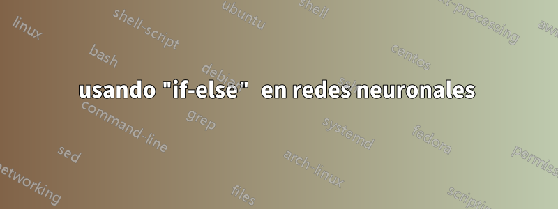
Me gustaría dibujar así:

Actualmente lo que tengo es
Mi código actual es
\begin{figure}
\centering
\label{fig:nn2}
\begin{tikzpicture}[shorten >=1pt,->,draw=black!50, node distance=\layersep]
    \tikzstyle{every pin edge}=[<-,shorten <=1pt]
    \tikzstyle{neuron}=[circle,fill=black!25,minimum size=17pt,inner sep=0pt]
    \tikzstyle{input neuron}=[neuron, fill=green!50];
    \tikzstyle{output neuron}=[neuron, fill=red!50];
    \tikzstyle{hidden neuron}=[neuron, fill=blue!50];
    \tikzstyle{annot} = [text width=4em, text centered]

    % Draw the input layer nodes
    \foreach \name / \y in {1,...,4}
    % This is the same as writing \foreach \name / \y in {1/1,2/2,3/3,4/4}
        %\if \y in {1,2,3,4}
        \node[input neuron, pin=left:Input \#\y] (I-\name) at (0,-\y) {$x_{\name}$};
        %\else
        %\node[input neuron, pin=left:Input \#\y] (I-\name) at (0,-\y) {$x_{\name}$};
    %\node[input neuron, pin=left:Input \#4] (+1) at (0,-4) {$x_{\name}$};

    % Draw the hidden layer nodes
    \foreach \name / \y in {1,...,4}
        \path[yshift=0.5cm]
            node[hidden neuron] (H-\name) at (\layersep,-\y cm) {$h_{\name}$};

    % Draw the output layer node
    \node[output neuron,pin={[pin edge={->}]right:Output}, right of=H-3] (O) {$y_{0}$};

    % Connect every node in the input layer with every node in the
    % hidden layer.
    \foreach \source in {1,...,4}
        \foreach \dest in {1,...,4}
            \path (I-\source) edge (H-\dest);

    % Connect every node in the hidden layer with the output layer
    \foreach \source in {1,...,4}
        \path (H-\source) edge (O);

    % Annotate the layers
    \node[annot,above of=H-1, node distance=1cm] (hl) {Hidden layer};
    \node[annot,left of=hl] {Input layer};
    \node[annot,right of=hl] {Output layer};
\end{tikzpicture}
\caption{A figure shows the structure of a general neural networks model}
\end{figure}
Intento usar "si-si no". y después de revisar, mi código es:
\begin{figure}
\centering
\label{fig:nn2}
\begin{tikzpicture}[shorten >=1pt,->,draw=black!50, node distance=\layersep]
    \tikzstyle{every pin edge}=[<-,shorten <=1pt]
    \tikzstyle{neuron}=[circle,fill=black!25,minimum size=17pt,inner sep=0pt]
    \tikzstyle{input neuron}=[neuron, fill=green!50];
    \tikzstyle{output neuron}=[neuron, fill=red!50];
    \tikzstyle{hidden neuron}=[neuron, fill=blue!50];
    \tikzstyle{annot} = [text width=4em, text centered]

    % Draw the input layer nodes
    \foreach \name / \y in {1,...,4}
    % This is the same as writing \foreach \name / \y in {1/1,2/2,3/3,4/4}
        \if \y in {1,2,3,4}
        \node[input neuron, pin=left:Input \#\y] (I-\name) at (0,-\y) {$x_{\name}$};
        \else
        %\node[input neuron, pin=left:Input \#\y] (I-\name) at (0,-\y) {$x_{\name}$};
    %\node[input neuron, pin=left:Input \#4] (+1) at (0,-4) {$x_{\name}$};

    % Draw the hidden layer nodes
    \foreach \name / \y in {1,...,4}
        \path[yshift=0.5cm]
            node[hidden neuron] (H-\name) at (\layersep,-\y cm) {$h_{\name}$};

    % Draw the output layer node
    \node[output neuron,pin={[pin edge={->}]right:Output}, right of=H-3] (O) {$y_{0}$};

    % Connect every node in the input layer with every node in the
    % hidden layer.
    \foreach \source in {1,...,4}
        \foreach \dest in {1,...,4}
            \path (I-\source) edge (H-\dest);

    % Connect every node in the hidden layer with the output layer
    \foreach \source in {1,...,4}
        \path (H-\source) edge (O);

    % Annotate the layers
    \node[annot,above of=H-1, node distance=1cm] (hl) {Hidden layer};
    \node[annot,left of=hl] {Input layer};
    \node[annot,right of=hl] {Output layer};
\end{tikzpicture}
\caption{A figure shows the structure of a general neural networks model}
\end{figure}
sin embargo, hay un error: Extra } u olvidado \endgroup
¡Gracias!
Respuesta1
Te faltaban las llaves alrededor del cuerpo del bucle y \fipara cerrar la declaración if. Además, la \ifdeclaración no funciona como pretendía:
\if<token1><token2>(pruebe si los códigos de caracteres coinciden)TeX expandirá las macros siguientes
\ifhasta que se encuentren dos tokens no expandibles. Si cualquiera de los tokens es una secuencia de control, TeX considera que tiene el código de carácter 256 y el código de categoría 16, a menos que el equivalente actual de esa secuencia de control haya sido\letigual a un token de carácter no activo. De esta manera, cada token especifica un par (código de carácter, código de categoría). La condición es verdadera si los códigos de caracteres son iguales, independientemente de los códigos de categoría. Por ejemplo, después de\def\a{*}y\let\b=*y\def\c{/}, las pruebas\if*\ay\if\a\bserán verdaderas, pero\if\a\cfalsas. También\if\a\parserá falso, pero\if\par\letserá verdadero.
(El TeXbook página 209)
Por lo tanto, estás comparando en el primer paso de iteración 1y i, en el segundo 2, y iasí sucesivamente, siempre evaluando como falso. En lugar de eso, estoy comprobando si es el último paso de iteración con \ifnum:
\begin{figure}
\centering
\label{fig:nn2}
\begin{tikzpicture}[shorten >=1pt,->,draw=black!50, node distance=\layersep]
    \tikzstyle{every pin edge}=[<-,shorten <=1pt]
    \tikzstyle{neuron}=[circle,fill=black!25,minimum size=17pt,inner sep=0pt]
    \tikzstyle{input neuron}=[neuron, fill=green!50];
    \tikzstyle{output neuron}=[neuron, fill=red!50];
    \tikzstyle{hidden neuron}=[neuron, fill=blue!50];
    \tikzstyle{annot} = [text width=4em, text centered]
    \newcommand{\n}{4} % number of neurons per layer

    % Draw the input layer nodes
    \foreach \name / \y in {1,...,\n}{
    % This is the same as writing \foreach \name / \y in {1/1,2/2,3/3,4/4}
        \ifnum \y=\n
            \node[input neuron, pin=left:Input \#$n$] (I-\name) at (0,-\y) {$x_{n}$};
        \else
            \node[input neuron, pin=left:Input \#\y] (I-\name) at (0,-\y) {$x_{\name}$};
        \fi
    }

    % Draw the hidden layer nodes
    \foreach \name / \y in {1,...,\n}{
        \ifnum \y=\n
            \path[yshift=0.5cm] node[hidden neuron] (H-\name) at (\layersep,-\y cm) {$h_{n}$};
        \else
            \path[yshift=0.5cm] node[hidden neuron] (H-\name) at (\layersep,-\y cm) {$h_{\name}$};
        \fi
    }

    % Draw the output layer node
    \node[output neuron,pin={[pin edge={->}]right:Output}, right of=H-3] (O) {$y_{0}$};

    % Connect every node in the input layer with every node in the
    % hidden layer.
    \foreach \source in {1,...,\n}
        \foreach \dest in {1,...,\n}
            \path (I-\source) edge (H-\dest);

    % Connect every node in the hidden layer with the output layer
    \foreach \source in {1,...,\n}
        \path (H-\source) edge (O);

    % Annotate the layers
    \node[annot,above of=H-1, node distance=1cm] (hl) {Hidden layer};
    \node[annot,left of=hl] {Input layer};
    \node[annot,right of=hl] {Output layer};
\end{tikzpicture}
\caption{A figure shows the structure of a general neural networks model}
\end{figure}
Sin embargo, no usaría ninguno si estuviera aquí:
\begin{figure}
\centering
\label{fig:nn2}
\begin{tikzpicture}[shorten >=1pt,->,draw=black!50, node distance=\layersep]
    \tikzstyle{every pin edge}=[<-,shorten <=1pt]
    \tikzstyle{neuron}=[circle,fill=black!25,minimum size=17pt,inner sep=0pt]
    \tikzstyle{input neuron}=[neuron, fill=green!50];
    \tikzstyle{output neuron}=[neuron, fill=red!50];
    \tikzstyle{hidden neuron}=[neuron, fill=blue!50];
    \tikzstyle{annot} = [text width=4em, text centered]
    \newcommand{\numberNeuronsPerLayer}{4}
    \edef\numberNeuronsPerLayerMinusOne{\number\numexpr\numberNeuronsPerLayer-1\relax}

    % Draw the input layer nodes
    \foreach \name / \y in {1,...,\numberNeuronsPerLayerMinusOne}{
    % This is the same as writing \foreach \name / \y in {1/1,2/2,3/3,4/4}
        \node[input neuron, pin=left:Input \#\y] (I-\name) at (0,-\y) {$x_{\name}$};
    }
    \node[input neuron, pin=left:Input \#$n$] (I-\numberNeuronsPerLayer) at (0,-\numberNeuronsPerLayer) {$x_{n}$};

    % Draw the hidden layer nodes
    \begin{scope}[yshift=0.5cm]
        \foreach \name / \y in {1,...,\numberNeuronsPerLayerMinusOne}{
            \path node[hidden neuron] (H-\name) at (\layersep,-\y cm) {$h_{\name}$};
        }
        \path node[hidden neuron] (H-\numberNeuronsPerLayer) at (\layersep,-\numberNeuronsPerLayer cm) {$h_{n}$};
    \end{scope}

    % Draw the output layer node
    \node[output neuron,pin={[pin edge={->}]right:Output}, right of=H-3] (O) {$y_{0}$};

    % Connect every node in the input layer with every node in the
    % hidden layer.
    \foreach \source in {1,...,\numberNeuronsPerLayer}
        \foreach \dest in {1,...,\numberNeuronsPerLayer}
            \path (I-\source) edge (H-\dest);

    % Connect every node in the hidden layer with the output layer
    \foreach \source in {1,...,\numberNeuronsPerLayer}
        \path (H-\source) edge (O);

    % Annotate the layers
    \node[annot,above of=H-1, node distance=1cm] (hl) {Hidden layer};
    \node[annot,left of=hl] {Input layer};
    \node[annot,right of=hl] {Output layer};
\end{tikzpicture}
\caption{A figure shows the structure of a general neural networks model}
\end{figure}
Respuesta2
Basado en mi respuesta a tu pregunta:

\documentclass[tikz, margin=3mm]{standalone}
\usetikzlibrary{calc, chains, positioning}

\begin{document}
    \begin{tikzpicture}[shorten >=1pt,->, draw=black!50,
        node distance = 6mm and 24mm,
          start chain = going below,
every pin edge/.style = {<-,shorten <=1pt},
        neuron/.style = {circle, fill=#1,
                         minimum size=17pt, inner sep=0pt},
         annot/.style = {text width=4em, align=center}
                        ]
% Draw the input and hidden layer nodes
\ifnum\i<4
    \node[neuron=green!50, on chain,
          pin=180:Input \#\i    % if you not like to have this inputs, just erase them
          ]              (I-\i)  {$x_{\i}$};
    \node[neuron=blue!50,
      right=of I-\i]     (H-\i)  {};
\else
    \node[neuron=green!50, on chain,
          pin=180:Input \#\i    % if you not like to have this inputs, just erase them
          ]              (I-\i)  {$+1$};
    \node[neuron=blue!50,
          right=of I-\i] (H-\i)  {$+1$};
\fi
}
% Draw the output layer node
    \node[neuron=red!50,
          right=of $(H-2)!0.5!(H-3)$]  (O-1)   {};
% Connect input nodes with hidden nodes and
%  hiden nodes with output nodes with the output layer
    \foreach \i in {1,...,4}
        \foreach \j in {1,...,4}
{
    \draw (I-\i) edge (H-\j)
          (H-\j) edge (O-1);
}
    \draw (O-1) -- node[below] {$h_{w,b}(x)$} + (2,0);
% Annotate layers
\node[annot,below=of I-4.center]        {Layer 1};
\node[annot,below=of H-4.center]        {Layer 2};
\node[annot,below=of O-1 |- H-4.center] {Layer 3};
    \end{tikzpicture}
\end{document}
Condicionales: como sigue desde arriba MWE
\ifnum\i<4
    action 1
\else
    action 2
\fi;
Apéndice: su problema lo puede resolver sin declaración condicional:
\documentclass[tikz, margin=3mm]{standalone}
\usetikzlibrary{calc, chains, positioning}

\begin{document}
    \begin{tikzpicture}[shorten >=1pt,->, draw=black!50,
        node distance = 6mm and 24mm,
          start chain = going below,
every pin edge/.style = {<-,shorten <=1pt},
        neuron/.style = {circle, fill=#1,
                         minimum size=17pt, inner sep=0pt},
         annot/.style = {text width=4em, align=center}
                        ]
% Draw the input and hyden layer nodes
\foreach \i in {1,2,3}
{
    \node[neuron=green!50, on chain,
          pin=180:Input \#\i    % if you not like to have this inputs, just erase them
          ]             (I-\i)  {$x_{\i}$};
    \node[neuron=blue!50,
      right=of I-\i]    (H-\i)     {};
}
    \node[neuron=green!50,
          pin=180:Input \#\i    % if you not like to have this inputs, just erase them
          below=of I-3
          ]              (I-4)  {$+1$};
    \node[neuron=blue!50,
          below=of H-3] (H-4)  {$+1$};
% Draw the output layer node
    \node[neuron=red!50,
          right=of $(H-2)!0.5!(H-3)$]  (O-1)   {};
% Connect input nodes with hidden nodes and
%  hiden nodes with output nodes with the output layer
    \foreach \i in {1,...,4}
        \foreach \j in {1,...,4}
{
    \draw (I-\i) edge (H-\j)
          (H-\j) edge (O-1);
}
    \draw (O-1) -- node[below] {$h_{w,b}(x)$} + (2,0);
% Annotate layers
\node[annot,below=of I-4.center]        {Layer 1};
\node[annot,below=of H-4.center]        {Layer 2};
\node[annot,below=of O-1 |- H-4.center] {Layer 3};
    \end{tikzpicture}
\end{document}
El resultado es el mismo que antes.